IRDC3812 International Rectifier, IRDC3812 Datasheet - Page 4
IRDC3812
Manufacturer Part Number
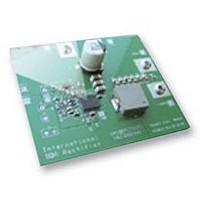
IRDC3812
Description
BOARD EVAL SYNC BUCK CONVERTER
Manufacturer
International Rectifier
Specifications of IRDC3812
Silicon Manufacturer
International Rectifier
Kit Application Type
Power Management - Voltage Regulator
Application Sub Type
Synchronous Buck Converter
Features
Programmable Soft Start, Programmable
Rohs Compliant
Yes


11/04/08
Pin Description
Pins 4, 5 and 15 need to be connected together on system board.
Pin
10
11
12
13
14
15
1
2
3
4
5
6
7
8
9
Name
SS/SD
OCSet
Comp
AGnd
AGnd
PGnd
AGnd
Vref
V
SW
HG
V
Vp
Fb
V
CC
IN
C
Output of error amplifier. An external resistor and capacitor network is typically
Non-inverting input of error amplifier. This pin can be used for tracking application.
Inverting input to the error amplifier. This pin is connected directly to the output of
the regulator via resistor divider to set the output voltage and provide feedback to
the error amplifier.
connected from this pin to ground to provide loop compensation.
Signal ground for internal reference and control circuitry.
Signal ground for internal reference and control circuitry.
Soft start / shutdown. This pin provides user programmable soft-start function.
Connect an external capacitor from this pin to ground to set the start up time of the
output voltage. The converter can be shutdown by pulling this pin below 0.3V.
Current limit set point. A resistor from this pin to SW pin will set the current limit
threshold.
This pin powers the internal IC as well as low side driver. A minimum of 0.1uF high
frequency capacitor must be connected from this pin to the power ground.
External reference voltage. Drive capability for this pin is 2μA.
Power Ground. This pin serves as a separated ground for the MOSFET drivers and
should be connected to the system’s power ground plane.
Switch node. This pin is connected to the output inductor
Input voltage connection pin
This pin is connected to the high side gate driver. Connect a small capacitor from
this pin to switch node (SW).
This pin powers the high side driver and must be connected to a voltage higher than
input voltage. A minimum of 0.1uF high frequency capacitor must be connected
from this pin to the power ground for the charge-pump high side drive scheme.
Signal ground for internal reference and control circuitry.
Description
IR3812MPbF
PD-60335
4
Related parts for IRDC3812
Image
Part Number
Description
Manufacturer
Datasheet
Request
R

Part Number:
Description:
SCHOTTKY RECTIFIER
Manufacturer:
International Rectifier Corp.
Datasheet:
Part Number:
Description:
SCHOTTKY RECTIFIER
Manufacturer:
International Rectifier Corp.
Datasheet:
Part Number:
Description:
SCHOTTKY RECTIFIER
Manufacturer:
International Rectifier Corp.
Datasheet:
Part Number:
Description:
SCHOTTKY RECTIFIER
Manufacturer:
International Rectifier Corp.
Datasheet:
Part Number:
Description:
SCHOTTKY RECTIFIER
Manufacturer:
International Rectifier Corp.
Datasheet:
Part Number:
Description:
SCHOTTKY RECTIFIER
Manufacturer:
International Rectifier Corp.
Datasheet:
Part Number:
Description:
SCHOTTKY RECTIFIER
Manufacturer:
International Rectifier Corp.
Datasheet:
Part Number:
Description:
SCHOTTKY RECTIFIER
Manufacturer:
International Rectifier Corp.
Datasheet:
Part Number:
Description:
SCHOTTKY RECTIFIER
Manufacturer:
International Rectifier Corp.
Datasheet:
Part Number:
Description:
SCHOTTKY RECTIFIER
Manufacturer:
International Rectifier Corp.
Datasheet:
Part Number:
Description:
SCHOTTKY RECTIFIER
Manufacturer:
International Rectifier Corp.
Datasheet:
Part Number:
Description:
SCHOTTKY RECTIFIER
Manufacturer:
International Rectifier Corp.
Datasheet:
Part Number:
Description:
SCHOTTKY RECTIFIER
Manufacturer:
International Rectifier Corp.
Datasheet:
Part Number:
Description:
SCHOTTKY RECTIFIER
Manufacturer:
International Rectifier Corp.
Datasheet:
Part Number:
Description:
SCHOTTKY RECTIFIER
Manufacturer:
International Rectifier Corp.
Datasheet: