LM2831XMF EVAL National Semiconductor, LM2831XMF EVAL Datasheet - Page 12
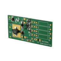
LM2831XMF EVAL
Manufacturer Part Number
LM2831XMF EVAL
Description
EVAL BOARD FOR LM2831XMF
Manufacturer
National Semiconductor
Specifications of LM2831XMF EVAL
Main Purpose
DC/DC, Step Down
Outputs And Type
1, Non-Isolated
Voltage - Output
0.6 ~ 5.5V
Current - Output
1.5A
Voltage - Input
3 ~ 5.5V
Regulator Topology
Buck
Frequency - Switching
1.6MHz
Board Type
Fully Populated
Utilized Ic / Part
LM2831
Lead Free Status / RoHS Status
Contains lead / RoHS non-compliant
Power - Output
-
Other names
*LM2831XMF EVAL
LM2831XMFEVAL
LM2831XMFEVAL


www.national.com
Design Guide
In general,
If ∆i
1.8A. The minimum guaranteed current limit over all operat-
ing conditions is 1.8A. One can either reduce ∆i
the engineering judgment that zero margin will be safe
enough. The typical current limit is 2.5A.
The LM2831 operates at frequencies allowing the use of
ceramic output capacitors without compromising transient
response. Ceramic capacitors allow higher inductor ripple
without significantly increasing output ripple. See the output
capacitor section for more details on calculating output volt-
age ripple. Now that the ripple current is determined, the
inductance is calculated by:
Where
When selecting an inductor, make sure that it is capable of
supporting the peak output current without saturating. Induc-
tor saturation will result in a sudden reduction in inductance
and prevent the regulator from operating correctly. Because
of the speed of the internal current limit, the peak current of
the inductor need only be specified for the required maxi-
mum output current. For example, if the designed maximum
output current is 1.0A and the peak current is 1.25A, then the
inductor should be specified with a saturation current limit of
current of the inductor at the 2.5A typical switch current limit.
The difference in inductor size is a factor of 5. Because of the
operating frequency of the LM2831, ferrite based inductors
are preferred to minimize core losses. This presents little
restriction since the variety of ferrite-based inductors is
huge. Lastly, inductors with lower series resistance (R
will provide better operating efficiency. For recommended
inductors see Example Circuits.
>
1.25A. There is no need to specify the saturation or peak
L
= 20% of 1.50A, the peak current in the inductor will be
∆i
FIGURE 3. Inductor Current
L
= 0.1 x (I
(Continued)
OUT
) → 0.2 x (I
OUT
)
L
, or make
DCR
20174805
)
12
INPUT CAPACITOR
An input capacitor is necessary to ensure that V
drop excessively during switching transients. The primary
specifications of the input capacitor are capacitance, volt-
age, RMS current rating, and ESL (Equivalent Series Induc-
tance). The recommended input capacitance is 22 µF.The
input voltage rating is specifically stated by the capacitor
manufacturer. Make sure to check any recommended derat-
ings and also verify if there is any significant change in
capacitance at the operating input voltage and the operating
temperature. The input capacitor maximum RMS input cur-
rent rating (I
Neglecting inductor ripple simplifies the above equation to:
It can be shown from the above equation that maximum
RMS capacitor current occurs when D = 0.5. Always calcu-
late the RMS at the point where the duty cycle D is closest to
0.5. The ESL of an input capacitor is usually determined by
the effective cross sectional area of the current path. A large
leaded capacitor will have high ESL and a 0805 ceramic chip
capacitor will have very low ESL. At the operating frequen-
cies of the LM2831, leaded capacitors may have an ESL so
large that the resulting impedance (2πfL) will be higher than
that required to provide stable operation. As a result, surface
mount capacitors are strongly recommended.
Sanyo POSCAP, Tantalum or Niobium, Panasonic SP, and
multilayer ceramic capacitors (MLCC) are all good choices
for both input and output capacitors and have very low ESL.
For MLCCs it is recommended to use X7R or X5R type
capacitors due to their tolerance and temperature character-
istics. Consult capacitor manufacturer datasheets to see
how rated capacitance varies over operating conditions.
OUTPUT CAPACITOR
The output capacitor is selected based upon the desired
output ripple and transient response. The initial current of a
load transient is provided mainly by the output capacitor. The
output ripple of the converter is:
When using MLCCs, the ESR is typically so low that the
capacitive ripple may dominate. When this occurs, the out-
put ripple will be approximately sinusoidal and 90˚ phase
shifted from the switching action. Given the availability and
quality of MLCCs and the expected output voltage of designs
using the LM2831, there is really no need to review any other
capacitor technologies. Another benefit of ceramic capaci-
tors is their ability to bypass high frequency noise. A certain
amount of switching edge noise will couple through parasitic
capacitances in the inductor to the output. A ceramic capaci-
tor will bypass this noise while a tantalum will not. Since the
output capacitor is one of the two external components that
control the stability of the regulator control loop, most appli-
cations will require a minimum of 22 µF of output capaci-
tance. Capacitance often, but not always, can be increased
RMS-IN
) must be greater than:
IN
does not
Related parts for LM2831XMF EVAL
Image
Part Number
Description
Manufacturer
Datasheet
Request
R

Part Number:
Description:
IC REGULATOR BUCK 1.5A SOT23-5
Manufacturer:
National Semiconductor
Datasheet:
Part Number:
Description:
IC,SMPS CONTROLLER,CURRENT-MODE,TSOP,5PIN,PLASTIC
Manufacturer:
National Semiconductor
Part Number:
Description:
National Semiconductor [8-Bit D/A Converter]
Manufacturer:
National Semiconductor
Datasheet:
Part Number:
Description:
National Semiconductor [Media Coprocessor]
Manufacturer:
National Semiconductor
Datasheet:
Part Number:
Description:
Digitally Controlled Tone and Volume Circuit with Stereo Audio Power Amplifier, Microphone Preamp Stage and National 3D Sound
Manufacturer:
National Semiconductor
Datasheet:
Part Number:
Description:
Digitally Controlled Tone and Volume Circuit with Stereo Audio Power Amplifier, Microphone Preamp Stage and National 3D Sound
Manufacturer:
National Semiconductor
Datasheet:
Part Number:
Description:
AC97 Rev 2 Codec with Sample Rate Conversion and National 3D Sound
Manufacturer:
National Semiconductor
Part Number:
Description:
Manufacturer:
National Semiconductor
Datasheet:
Part Number:
Description:
Manufacturer:
National Semiconductor
Datasheet:
Part Number:
Description:
General Purpose, Low Voltage, Low Power, Rail-to-Rail Output Operational Amplifiers
Manufacturer:
National Semiconductor
Datasheet:
Part Number:
Description:
8-bit 20 MSPS flash A/D converter.
Manufacturer:
National Semiconductor
Datasheet:
Part Number:
Description:
Low Noise Quad Operational Amplifier
Manufacturer:
National Semiconductor
Datasheet:
Part Number:
Description:
Quad Differential Line Receivers
Manufacturer:
National Semiconductor
Datasheet:
Part Number:
Description:
Quad High Speed Trapezoidal? Bus Transceiver
Manufacturer:
National Semiconductor
Datasheet: