LM25574EVAL National Semiconductor, LM25574EVAL Datasheet - Page 2
LM25574EVAL
Manufacturer Part Number
LM25574EVAL
Description
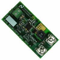
BOARD EVALUATION FOR LM25574
Manufacturer
National Semiconductor
Series
PowerWise®, SIMPLE SWITCHER®r
Specifications of LM25574EVAL
Main Purpose
DC/DC, Step Down
Outputs And Type
1, Non-Isolated
Voltage - Output
5V
Current - Output
500mA
Voltage - Input
7 ~ 42V
Regulator Topology
Buck
Frequency - Switching
300kHz
Board Type
Fully Populated
Utilized Ic / Part
LM25574
Lead Free Status / RoHS Status
Not applicable / Not applicable
Power - Output
-
Other names
*LM25574EVAL


www.national.com
activate. A stand-alone fan with at lease 200 LFM should al-
ways be provided.
POWERING UP
Using the shutdown pin provided will allow powering up the
source supply with the current level set low. It is suggested
that the load be kept low during the first power up. Set the
current limit of the source supply to provide about 1.5 times
the anticipated wattage of the load. As you remove the con-
nection from the shutdown pin to ground, immediately check
for 5 volts at the output.
A quick efficiency check is the best way to confirm that ev-
erything is operating properly. If something is amiss you can
be reasonably sure that it will affect the efficiency adversely.
Few parameters can be incorrect in a switching power supply
without creating losses and potentially damaging heat.
OVER CURRENT PROTECTION
The evaluation board is configured with over-current protec-
tion. The output current is limited to approximately 0.7A. The
thermal stress is quite severe while in an overloaded condi-
tion, limit the duration of the overload and provide sufficient
cooling (airflow).
SYNCHRONIZATION
A SYNC pin has been provided on the evaluation board. This
pin can be used to synchronize the regulator to an external
clock or multiple evaluation boards can be synchronized to-
gether by connecting their SYNC pins together. Refer to the
LM25574 datasheet for complete information.
Performance Characteristics
EFFICIENCY PLOTS
Figure 1 shows the conversion efficiency versus output cur-
rent for several input voltage conditions.
FIGURE 1.
30006902
2
TURN-ON WAVEFORM
When applying power to the LM25574 evaluation board a
certain soft-start sequence occurs. Figure 2 shows the output
voltage during a typical start-up sequence.
Conditions: Input Voltage = 36VDC, Output Current = 0.4A
Trace 1: Output Voltage Volts/div = 2V
Horizontal Resolution = 500 µsec/div
OUTPUT RIPPLE WAVEFORM
Figure 3 shows the output voltage ripple. This measurement
was taken with a very short ground clip and 20MHZ bandwidth
limiting.
Conditions: Input Voltage = 36VDC Output Current = 0.4A Bandwidth Limit
= 20MHz
Trace 1: Output Ripple Voltage Volts/div = 50mV
Horizontal Resolution = 2 µsec/div
FIGURE 2.
FIGURE 3.
30006903
30006904
Related parts for LM25574EVAL
Image
Part Number
Description
Manufacturer
Datasheet
Request
R

Part Number:
Description:
National Semiconductor [8-Bit D/A Converter]
Manufacturer:
National Semiconductor
Datasheet:
Part Number:
Description:
National Semiconductor [Media Coprocessor]
Manufacturer:
National Semiconductor
Datasheet:
Part Number:
Description:
Digitally Controlled Tone and Volume Circuit with Stereo Audio Power Amplifier, Microphone Preamp Stage and National 3D Sound
Manufacturer:
National Semiconductor
Datasheet:
Part Number:
Description:
Digitally Controlled Tone and Volume Circuit with Stereo Audio Power Amplifier, Microphone Preamp Stage and National 3D Sound
Manufacturer:
National Semiconductor
Datasheet:
Part Number:
Description:
AC97 Rev 2 Codec with Sample Rate Conversion and National 3D Sound
Manufacturer:
National Semiconductor
Part Number:
Description:
Manufacturer:
National Semiconductor
Datasheet:
Part Number:
Description:
Manufacturer:
National Semiconductor
Datasheet:
Part Number:
Description:
General Purpose, Low Voltage, Low Power, Rail-to-Rail Output Operational Amplifiers
Manufacturer:
National Semiconductor
Datasheet:
Part Number:
Description:
8-bit 20 MSPS flash A/D converter.
Manufacturer:
National Semiconductor
Datasheet:
Part Number:
Description:
Low Noise Quad Operational Amplifier
Manufacturer:
National Semiconductor
Datasheet:
Part Number:
Description:
Quad Differential Line Receivers
Manufacturer:
National Semiconductor
Datasheet:
Part Number:
Description:
Quad High Speed Trapezoidal? Bus Transceiver
Manufacturer:
National Semiconductor
Datasheet:
Part Number:
Description:
Dual Line Receiver
Manufacturer:
National Semiconductor
Datasheet:
Part Number:
Description:
TTL to 10k ECL Level Translator with Latch
Manufacturer:
National Semiconductor
Datasheet: