NCP1423EVB ON Semiconductor, NCP1423EVB Datasheet
NCP1423EVB
Specifications of NCP1423EVB


Related parts for NCP1423EVB

NCP1423EVB Summary of contents
Page 1
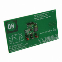
NCP1423 400 mA Sync−Rect PFM Step−Up DC−DC Converter with True−Cutoff and Ring−Killer NCP1423 is a monolithic micropower high frequency step−up switching converter IC specially designed for battery operated hand−held electronic products. It integrates Synchronous Rectifier for improving efficiency as well ...
Page 2
ON OFF 0 OUT PIN DESCRIPTION Pin No. Symbol 1 EN Low−Battery Detector Input and Enable. With this pin pulled down below 0.5 V, the device will be disabled and will enter ...
Page 3
ELECTRICAL CHARACTERISTICS = 25°C for typical value, −40° 3 OUT A Characteristic Operating Voltage Output Voltage Range Minimum Input Voltage for Startup Reference Voltage ( mA, Cref = 100 nF ...
Page 4
ZLC 0 Chip Enable 1 CONTROL LOGIC − PFM 1.2 V REF 2 Voltage Reference 0 LBI − 9 NCP1423 + − TRUE CUTOFF CONTROL _ZCUR _TSDON V DD _MSON ...
Page 5
TYPICAL OPERATING CHARACTERISTICS 1. REF 3.3 V OUT T = 25°C A 1.23 1.21 1.19 1.17 1. OUTPUT CURRENT (mA) LOAD Figure 3. Reference ...
Page 6
TYPICAL OPERATING CHARACTERISTICS 3.3 V OUT −50 − AMBIENT TEMPERATURE (°C) A Figure 9. LBI Input Current vs. Temperature 175 150 125 100 ...
Page 7
TYPICAL OPERATING CHARACTERISTICS 300 V = 3.3 V OUT 250 200 150 100 50 0 −50 − AMBIENT TEMPERATURE (°C) A Figure 15. EN Input Current vs. Temperature −2 = 3.3 V, ...
Page 8
TYPICAL OPERATING CHARACTERISTICS 250 = 3 5 OUT = 10 mF OUT 200 T = 25°C A 150 100 50 0 1.3 1.5 1.7 1.9 2 BATTERY ...
Page 9
TYPICAL OPERATING CHARACTERISTICS Upper Trace: Output Voltage Ripple, 50 mV/Division Lower Trace: Battery Voltage, V 1.0 V/Division IN 5 OUT Figure 27. Line Transient ...
Page 10
NCP1423 is a monolithic micropower high−frequency step−up voltage switching converter IC specially designed for battery operated hand−held electronic products up to 200 mA loading. It integrates a Synchronous Rectifier to improving efficiency as well as to eliminate the external Schottky ...
Page 11
IC is enabled again, and the internal circuit typically consumes current from the OUT pin during normal operation. Low−Battery Detection A comparator with 15 mV hysteresis is applied to perform the low−battery detection function. When Pin 9 ...
Page 12
General Design Procedures Switching mode converter design is important. Suitable choice an inductor and capacitor value can make the converter has an optimum performance. Below a simple method base on the most basic first order equations to estimate the inductor ...
Page 13
... SEATING H PLANE *For additional information on our Pb−Free strategy and soldering details, please download the ON Semiconductor Soldering and Mounting Techniques Reference Manual, SOLDERRM/D. SENSEFET is a trademark of Semiconductor Components Industries, LLC. ON Semiconductor and are registered trademarks of Semiconductor Components Industries, LLC (SCILLC). SCILLC reserves the right to make changes without further notice to any products herein ...