CDB4354 Cirrus Logic Inc, CDB4354 Datasheet
CDB4354
Specifications of CDB4354
CDB4354


Related parts for CDB4354


CDB4354 Summary of contents
Page 1
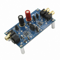
... Input Direct External Input http://www.cirrus.com Description The CDB4354 evaluation board is a dedicated platform designed to facilitate the evaluation of the CS4354 24- bit, stereo D/A converter. Evaluation requires an analog signal analyzer, a digital signal source, and pow- er supply. Analog line-level outputs are provided via RCA phono jacks ...
Page 2
... Figure 2. System Block Diagram and Signal Flow ...................................................................................... 7 Figure 3. CS8416 and CS4354 ................................................................................................................... 8 Figure 4. Power ........................................................................................................................................... 9 Figure 5. Silkscreen Top ........................................................................................................................... 10 Figure 6. Top Side ..................................................................................................................................... 10 Figure 6. Top Side ..................................................................................................................................... 10 Figure 7. Bottom Side ............................................................................................................................... 10 LIST OF TABLES Table 1. System Connections .................................................................................................................... 5 Table 2. CDB4354 Jumper Pin Block Settings ............................................................................................ 5 Table 3. LED Information ............................................................................................................................ 5 2 ........................................................................................................... 7 CDB4354 DS895DB1 ...
Page 3
... THE CDB4354 SYSTEM The CDB4354 is a dedicated platform for evaluating the CS4354. The CS8416 digital audio interface receiver pro- vides an easy interface to digital audio signal sources, including the majority of digital audio test equipment. The evaluation board also allows the user to supply external PCM clocks and data directly to the CS4354 through a head- er block for system development ...
Page 4
... Analog Output Filtering The analog output filter circuitry on the CDB4354 has been designed according to the CS4354 datasheet. This circuit is a first order resistor-capacitor low pass filter with values 470 /2.2 nF, respectively, which sets the -3 dB pole at 154 kHz. The resulting filter keeps signal attenuation below 0 kHz while provid- ing sufficient filtering for noise outside the audio band ...
Page 5
... Internal Serial Clock Mode, De-emphasis enabled *pins [2, 3] shunted External Serial Clock Mode, De-emphasis disabled not shunted Internal Serial Clock Mode, De-emphasis disabled Table 2. CDB4354 Jumper Pin Block Settings FUNCTION Table 3. LED Information CDB4354 SIGNAL PRESENT FUNCTION SELECTED Voltage source Voltage source is +3 ...
Page 6
... Figure 1. CDB4354 Factory Default Jumper Settings 6 CDB4354 DS895DB1 ...
Page 7
SCHEMATICS AND LAYOUT Hardware Controls CS8416 Manual Reset Optical S/PDIF CS8416 Input S/PDIF Coaxial S/PDIF Receiver Input Figure 3 Direct External Input Power: +5V Input, +3.3V Regulator Figure 3 CS4354 VL Select: De-emphasis 5V or 3.3V Select Serial Audio ...
Page 8
Figure 3. CS8416 and CS4354 ...
Page 9
Figure 4. Power ...
Page 10
... Note: Figure 5, 6, and 7 show the actual size of the CDB4354 if this document is printed on letter-sized paper. 10 Figure 5. Silkscreen Top Figure 6. Top Side Figure 7. Bottom Side CDB4354 DS895DB1 ...
Page 11
... TORNEYS’ FEES AND COSTS, THAT MAY RESULT FROM OR ARISE IN CONNECTION WITH THESE USES. Cirrus Logic, Cirrus, and the Cirrus Logic logo designs are trademarks of Cirrus Logic, Inc. All other brand and product names in this document may be trademarks or service marks of their respective owners. DS895DB1 Changes www.cirrus.com. CDB4354 11 ...