EVAL-AD5405EB Analog Devices Inc, EVAL-AD5405EB Datasheet - Page 15
EVAL-AD5405EB
Manufacturer Part Number
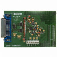
EVAL-AD5405EB
Description
BOARD EVAL FOR AD5405
Manufacturer
Analog Devices Inc
Specifications of EVAL-AD5405EB
Rohs Status
RoHS non-compliant
Number Of Dac's
2
Number Of Bits
12
Outputs And Type
2, Differential
Sampling Rate (per Second)
21.3M
Data Interface
Parallel
Settling Time
80ns
Dac Type
Current
Voltage Supply Source
Single Supply
Operating Temperature
-40°C ~ 125°C
Utilized Ic / Part
AD5405


Table 6 shows the relationship between the digital code and the
expected output voltage for bipolar operation.
Table 6. Bipolar Code
Digital Input
1111 1111 1111
1000 0000 0000
0000 0000 0001
0000 0000 0000
Stability
In the I-to-V configuration, the I
inverting node of the op amp must be connected as close as
possible, and proper PCB layout techniques must be used.
Because every code change corresponds to a step function, gain
peaking may occur if the op amp has limited gain bandwidth
product (GBP) and there is excessive parasitic capacitance at the
inverting node. This parasitic capacitance introduces a pole into
the open-loop response, which can cause ringing or instability
in the closed-loop applications circuit.
An optional compensation capacitor, C1, can be added in parallel
with R
small a value of C1 can produce ringing at the output, whereas
too large a value can adversely affect the settling time. C1 should
be found empirically, but 1 pF to 2 pF is generally adequate for
the compensation.
SINGLE-SUPPLY APPLICATIONS
Voltage-Switching Mode of Operation
Figure 34 shows the DAC operating in the voltage-switching
mode. The reference voltage, V
I
available at the V
reference voltage results in a positive output voltage, making
single-supply operation possible. The output from the DAC is
voltage at a constant impedance (the DAC ladder resistance).
Therefore, an op amp is necessary to buffer the output voltage.
The reference input no longer sees a constant input impedance,
but one that varies with code. Therefore, the voltage input
should be driven from a low impedance source.
V
OUT
IN
2A is connected to AGND, and the output voltage is
FB
A for stability, as shown in Figure 32 and Figure 33. Too
NOTES
1. SIMILAR CONFIGURATION FOR DAC B.
2. C1 PHASE COMPENSATION (1pF TO 2pF) MAY BE REQUIRED
Figure 34. Single-Supply Voltage-Switching Mode
I
I
OUT
OUT
IF A1 IS A HIGH SPEED AMPLIFIER.
1A
2A
R
REF
FB
A V
A terminal. In this configuration, a positive
GND
V
DD
DD
+V
0
−V
−V
Analog Output (V)
V
REF
REF
REF
REF
IN
A
, is applied to the I
OUT
(4,095/4,096)
(4,095/4,096)
(4,096/4,096)
of the DAC and the
R
1
R
2
OUT
1A pin,
V
OUT
Rev. B | Page 15 of 24
Note that V
DAC ladder no longer have the same source-drain drive voltage.
As a result, their on resistance differs and degrades the integral
linearity of the DAC. Also, V
than 0.3 V, or an internal diode turns on, causing the device to
exceed the maximum ratings. In this type of application, the full
range of multiplying capability of the DAC is lost.
Positive Output Voltage
The output voltage polarity is opposite to the V
dc reference voltages. To achieve a positive voltage output, an
applied negative reference to the input of the DAC is preferred
over the output inversion through an inverting amplifier because
of the resistor’s tolerance errors. To generate a negative reference,
the reference can be level-shifted by an op amp such that the
V
and −2.5 V, respectively, as shown in Figure 35.
ADDING GAIN
In applications where the output voltage must be greater than
V
it can be achieved in a single stage. Consider the effect of temper-
ature coefficients of the thin film resistors of the DAC. Simply
placing a resistor in series with the R
in the temperature coefficients, resulting in larger gain temper-
ature coefficient errors. Instead, the circuit of Figure 36 shows
the recommended method for increasing the gain of the circuit.
R1, R2, and R3 should have similar temperature coefficients,
but they need not match the temperature coefficients of the DAC.
This approach is recommended in circuits where gains of greater
than 1 are required.
OUT
IN
, gain can be added with an additional external amplifier, or
and GND pins of the reference become the virtual ground
–5V
Figure 35. Positive Voltage Output with Minimum Components
+
5V
V
ADR03
OUT
IN
GND
NOTES
1. SIMILAR CONFIGURATION FOR DAC B.
2. C1 PHASE COMPENSATION (1pF TO 2pF) MAY BE REQUIRED
–2.5V
is limited to low voltages because the switches in the
IF A1 IS A HIGH SPEED AMPLIFIER.
V
IN
V
REF
A
V
12-BIT DAC
DD
GND
V
DD
= +5V
IN
must not go negative by more
R
FB
I
I
OUT
OUT
A
1A
2A
FB
resistor causes mismatches
C
1
REF
polarity for
V
OUT
AD5405
= 0V TO +2.5V
Related parts for EVAL-AD5405EB
Image
Part Number
Description
Manufacturer
Datasheet
Request
R

Part Number:
Description:
ENERCHIP CC EVAL KIT
Manufacturer:
Cymbet Corporation
Datasheet:

Part Number:
Description:
BOARD EVAL FOR AD976
Manufacturer:
Analog Devices Inc
Datasheet:

Part Number:
Description:
BOARD EVAL FOR ADXL345
Manufacturer:
Analog Devices Inc
Datasheet:

Part Number:
Description:
ENERCHIP CC SEH EVAL KIT
Manufacturer:
Cymbet Corporation
Datasheet:

Part Number:
Description:
ENERCHIP EP ENERGY HARVEST EVAL
Manufacturer:
Cymbet Corporation
Datasheet:

Part Number:
Description:
EVAL BOARD FOR TW6864-LB2-GR
Manufacturer:
Intersil
Datasheet:
Part Number:
Description:
EVAL BOARD FOR TW8816-LB3-GR
Manufacturer:
Intersil
Datasheet:
Part Number:
Description:
EVAL BOARD FOR TW8817-TA3-GRS
Manufacturer:
Intersil
Datasheet:

Part Number:
Description:
EVALUATION MODULE FOR ADUM4160
Manufacturer:
Analog Devices Inc
Datasheet:

Part Number:
Description:
BOARD EVALUATION ADCMP581BCP
Manufacturer:
Analog Devices Inc
Datasheet:
Part Number:
Description:
BOARD EVALUATION ADM1041
Manufacturer:
Analog Devices Inc
Datasheet:

Part Number:
Description:
EVAL BOARD FOR STM32F107VCT
Manufacturer:
STMicroelectronics
Datasheet:
Part Number:
Description:
BOARD EVAL FOR AD1954
Manufacturer:
Analog Devices Inc
Datasheet:
Part Number:
Description:
BOARD EVAL FOR AD1955
Manufacturer:
Analog Devices Inc
Datasheet:

Part Number:
Description:
BOARD EVAL FOR AD7655
Manufacturer:
Analog Devices Inc
Datasheet: