EVAL-AD5764EBZ Analog Devices Inc, EVAL-AD5764EBZ Datasheet - Page 20
EVAL-AD5764EBZ
Manufacturer Part Number
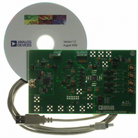
EVAL-AD5764EBZ
Description
BOARD EVAL FOR AD5764
Manufacturer
Analog Devices Inc
Specifications of EVAL-AD5764EBZ
Number Of Dac's
4
Number Of Bits
16
Outputs And Type
4, Single Ended
Sampling Rate (per Second)
30M
Data Interface
Serial
Settling Time
8µs
Dac Type
Voltage
Voltage Supply Source
Dual ±
Operating Temperature
-40°C ~ 85°C
Utilized Ic / Part
AD5764
Lead Free Status / RoHS Status
Lead free / RoHS Compliant


AD5764
TRANSFER FUNCTION
Table 7 and Table 8 show the ideal input code to output voltage
relationship for the AD5764 for both offset binary and twos
complement data coding, respectively.
Table 7. Ideal Output Voltage to Input Code Relationship—
Offset Binary Data Coding
MSB
1111
1000
1000
0111
0000
Table 8. Ideal Output Voltage to Input Code Relationship—
Twos Complement Data Coding
MSB
0111
0000
0000
1111
1000
Table 9. Input Shift Register Bit Map
MSB
DB23 DB22 DB21 DB20 DB19 DB18 DB17 DB16
R/W
Table 10. Input Shift Register Bit Functions
Bit
R/W
REG2, REG1, REG0
A2, A1, A0
Data
0
1111
0000
0000
1111
0000
1111
0000
0000
1111
0000
Digital Input
Digital Input
REG2
1111
0000
0000
1111
0000
1111
0000
0000
1111
0000
REG1
Description
Indicates a read from or a write to the addressed register.
Used in association with the address bits to determine if a read or write operation is to the data register, offset
register, coarse gain register, fine gain register, or function register.
REG2
0
0
0
1
1
These bits are used to decode the DAC channels.
A2
0
0
0
0
1
Data bits.
LSB
1111
0001
0000
1111
0000
LSB
1111
0001
0000
1111
0000
REG0
Analog Output
VOUTx
+2 V
+2 V
0 V
−2 V
−2 V
Analog Output
VOUTx
+2 V
+2 V
0 V
−2 V
−2 V
REG1
0
1
1
0
0
A1
0
0
1
1
0
A2
REF
REF
REF
REF
REF
REF
REF
REF
× (32,767/32,768)
× (1/32,768)
× (1/32,768)
× (32,767/32,768)
× (32,767/32,768)
× (1/32,768)
× (1/32,768)
× (32,767/32,768)
A1
REG0
0
0
1
0
1
A0
0
1
0
1
0
A0
Function
Function register
Data register
Coarse gain register
Fine gain register
Offset register
Channel Address
DAC A
DAC B
DAC C
DAC D
All DACs
Rev. D | Page 20 of 28
The output voltage expression for the AD5764 is given by
where:
D is the decimal equivalent of the code loaded to the DAC.
V
ASYNCHRONOUS CLEAR (CLR)
CLR is a negative edge triggered clear that allows the outputs to
be cleared to either 0 V (twos complement coding) or negative
full scale (offset binary coding). It is necessary to maintain CLR
low for a minimum amount of time (see
to complete. When the
remains at the cleared value until a new value is programmed. If
at power-on, CLR is at 0 V, then all DAC outputs are updated
with the clear value. A clear can also be initiated through software
by writing Command 0x04XXXX to the AD5764.
REFIN
V
is the reference voltage applied at the REFAB/REFCD pins.
OUT
=
−
2
×
V
REFIN
DB15:DB0
CLR signal is returned high, the output
+
Data
4
×
V
REFIN
⎡
⎢
⎣
65
Figure 2
D
,
536
⎤
⎥
⎦
) for the operation
LSB
Related parts for EVAL-AD5764EBZ
Image
Part Number
Description
Manufacturer
Datasheet
Request
R


Part Number:
Description:
BOARD EVAL FOR SI270X-A
Manufacturer:
Silicon Laboratories Inc
Datasheet:

Part Number:
Description:
BUCK CONV REF DESIGN KIT IP1201
Manufacturer:
International Rectifier
Datasheet:
Part Number:
Description:
BOARD DEMO SYNC DUAL BUCK CNVTER
Manufacturer:
International Rectifier
Datasheet:
Part Number:
Description:
BOARD DEMO SYNC BUCK CONVETER
Manufacturer:
International Rectifier
Datasheet:

Part Number:
Description:
EVALBOARD/EB Omnidirectional microphone - Analog
Manufacturer:
Analog Devices
Datasheet:
Part Number:
Description:
EVALBOARD/EB Omnidirectional microphone - Analog
Manufacturer:
Analog Devices
Datasheet:


Part Number:
Description:
BOARD EVAL LED DRIVER LT3756
Manufacturer:
Linear Technology
Datasheet:

Part Number:
Description:
BOARD EVAL FOR AD7741/7742
Manufacturer:
Analog Devices Inc
Datasheet:

Part Number:
Description:
±1.7g Dual-Axis IMEMS Accelerometer Evaluation Board
Manufacturer:
Analog Devices Inc
Datasheet:

Part Number:
Description:
IC MULTIPLIER ANALOG 8-SOIC T/R
Manufacturer:
Analog Devices Inc
Datasheet:

Part Number:
Description:
IC ANALOG MULTIPLIER 8-DIP
Manufacturer:
Analog Devices Inc
Datasheet:
Part Number:
Description:
IC ANALOG MULTIPLIER 8-SOIC
Manufacturer:
Analog Devices Inc
Datasheet:
Part Number:
Description:
IC ANALOG MULTIPLIER 8-DIP
Manufacturer:
Analog Devices Inc
Datasheet: