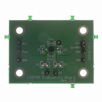
LM2793LDEV National Semiconductor, LM2793LDEV Datasheet - Page 8

LM2793LDEV
Manufacturer Part Number
LM2793LDEV
Description
BOARD EVALUATION LM2793LD
Manufacturer
National Semiconductor
Series
PowerWise®r
Specifications of LM2793LDEV
Current - Output / Channel
16mA
Outputs And Type
2, Non-Isolated
Voltage - Output
4 V
Features
Charge Pump
Voltage - Input
2.7 ~ 5.5V
Utilized Ic / Part
LM2793
Lead Free Status / RoHS Status
Not applicable / Not applicable
www.national.com
Application Information
PARALLEL DX OUTPUTS FOR INCREASED CURRENT
DRIVE
Outputs D
single LED. In such a configuration, two parallel current
sources of equal value drive the single LED. The voltage on
SD-BRGT should be chosen so that the current through
each of the outputs is programmed to 50% of the total
desired LED current. For example, if 30mA is the desired
drive current for the single LED, SD-BRGT should be se-
lected so that the current through each of the outputs is
15mA. Connecting the outputs in parallel does not affect
internal operation of the LM2793 and has no impact on the
Electrical Characteristics and limits previously presented.
The available diode output current, maximum diode voltage,
and all other specifications provided in the Electrical Char-
acteristics table apply to this parallel output configuration,
just as they do to the standard 2-LED application circuit.
P
P
the LM2793 1.5x charge pump. Pre-regulation uses the
voltage present at P
switched capacitor charge pump. Pre-regulation helps to
reduce input current noise and large input current spikes
normally associated with switched capacitor charge pumps.
At voltages below 3.3V (typ.), the LM2793 acts as an open
loop charge pump. When the device is in open loop, the
voltage at P
voltages higher than 3.3V (typ.) P
4.9V (typ.).
POWER EFFICIENCY
Figure 2 shows the efficiency of the LM2793.
Efficiency (E) of the LM2793 is defined here as the ratio of
the power consumed by LEDs (P
from the input source (P
quiescent current of the LM2793, I
OUT
OUT
Manufacturer
uses pre-regulation to loosely regulate the output of
Osram
Nichia
1
2 LEDs, V
and D
OUT
TABLE 2. White LED Selection
FIGURE 2. Efficiency vs. V
is 1.5 times the input voltage. At input
2
may be connected together to drive a
OUT
LED
IN
to limit the gate drive of the 1.5x
). In the equations below, I
= 3.6V, I
www.osram-os.com
www.nichia.com
OUT
LED
LED
LED
Contact
is loosely regulated to
) to the power drawn
is the current flowing
= 16mA
(Continued)
IN
20063612
Q
is the
8
through one LED, and V
LED current. In the input power calculation, the 1.5 multiplier
reflects the 3/2 switched capacitor gain of the LM2793.
It is also worth noting that efficiency as defined here is in part
dependent on LED voltage. Variation in LED voltage does
not affect power consumed by the circuit and typically does
not relate to the brightness of the LED. For an advanced
analysis, it is recommended that power consumed by the
circuit (V
Power consumption of the LM2793 Typical Application Cir-
cuit is shown in Figure 3.
THERMAL PROTECTION
When the junction temperature exceeds 150˚C, the LM2793
internal thermal protection circuitry disables the part. This
feature protects the device from damage due to excessive
power dissipation. The device will recover and operate nor-
mally when the junction temperature falls below 125˚C. It is
important to have good thermal conduction with a proper
layout to reduce thermal resistance.
POWER DISSIPATION
When operating within specified operating ratings, the peak
power dissipation (P
input voltage of 5.5V. Assuming a typical junction-to-ambient
thermal resistance (θJA) for the LLP-10 package of 55˚C/W,
a LED forward voltage (V
of 32mA for two White LEDs connected to D
power dissipation and junction temperature (T
lated below for a part operating at the maximum rated am-
bient temperature (T
the input voltage to the LM2793, P
by the 1.5x charge pump, and P
by the LEDs.
IN
2 LEDs, 2.5 ≤ V
x I
P
FIGURE 3. I
= ((1.5 x 5.5V) - 3.6V) x 0.032A
IN
IN
) be evaluated rather than power efficiency.
P
= (1.5V
= V
P
DISSIPATION
LED
DISSIPATION
A
IN
E = (P
) of 85˚C. In the equations below, V
P
= N x V
x (1.5 x N x I
IN
DX
IN
= 149mW
LED
LED
LED
= V
) of 3.6V, and a total load (I
− V
LED
is the forward voltage at that
≤ 3.9V, I
IN
= P
current vs. P
DX
) of the LM2793 occurs at an
LED
÷ P
LED
x I
) x I
IN
IN
IN
x I
IN
- P
is the power consumed
is the power generated
LED
)
LOAD
LED
LED
LED
+ I
= 16mA
Q
IN
20063613
)
1
J
and D
) are calcu-
LOAD
2
, the
IN
is
)


