NCP1351LEDGEVB ON Semiconductor, NCP1351LEDGEVB Datasheet - Page 20
NCP1351LEDGEVB
Manufacturer Part Number
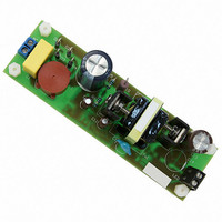
NCP1351LEDGEVB
Description
EVAL BOARD FOR NCP1351LEDG
Manufacturer
ON Semiconductor
Datasheets
1.NCP1351APG.pdf
(27 pages)
2.NCP1351LEDGEVB.pdf
(11 pages)
3.NCP1351LEDGEVB.pdf
(3 pages)
Specifications of NCP1351LEDGEVB
Design Resources
NCP1351 EVB BOM NCP1351LEDGEVB Gerber Files NCP1351LED EVB Schematic
Current - Output / Channel
700mA
Outputs And Type
1, Isolated
Voltage - Output
33V
Features
Short-Circuit Protection
Voltage - Input
85 ~ 265 V
Utilized Ic / Part
NCP1351
Core Chip
NCP1351
Topology
Flyback
No. Of Outputs
1
Output Current
700mA
Output Voltage
33V
Development Tool Type
Hardware - Eval/Demo Board
Leaded Process Compatible
Yes
Rohs Compliant
Yes
Lead Free Status / RoHS Status
Lead free / RoHS Compliant
For Use With/related Products
NCP1351LEDG
Other names
NCP1351LEDGEVBOS


Let us round it to 0.25 or 1/N = 4
50%. The design should thus be free of subharmonic
oscillations in steady-state conditions. If necessary,
negative ramp compensation is however feasible by the
auxiliary winding.
where K = DI
in CCM (see Figure 26).
•
•
d max +
L +
In this equation, the CCM duty-cycle does not exceed
Small K: deep CCM, implying a large primary
inductance, a low bandwidth and a large leakage
inductance.
Large K: approaching BCM where the RMS losses are
the worse, but smaller inductance, leading to a better
leakage inductance.
Figure 26. Primary Inductance Current Evolution
2. Calculate the maximum operating duty-cycle for
3. To obtain the primary inductance, we can use the
( V in_min d max ) 2
this flyback converter operated in CCM:
following equation which expresses the inductance
in relationship to a coefficient k. This coefficient
actually dictates the depth of the CCM operation.
If it goes to 2, then we are in DCM.
DT
F SW KP in
SW
V out N ) V in_min
L
/I
I
V out N
and defines the amount of ripple we want
T
SW
in CCM
I
1
+
19
19
4 ) 100
I
I
I
peak
valley
valley
I
4
avg
+ 0.43
(eq. 21)
(eq. 22)
DI
http://onsemi.com
L
t
NCP1351
20
From Equation 17, a K factor of 0.8 (40% ripple) ensures a
good operation over universal mains. It leads to an
inductance of:
The peak current can be evaluated to be:
On Figure 26,
The valley current is also found to be:
To generate 1 V, the offset resistor will be 3.7 kW, as already
explained. Using Equation 29, the power dissipated in the
sense element reaches:
Figure 27 portrays a possible application schematic
implementing what we discussed in the above lines.
L +
DI L +
I in_avg +
I peak +
I valley + I peak * DI L + 2.33 * 1.34 + 1.0 A
I d_rms + I I d
R sense +
P sense + R sense I d_rms 2 + 0.4
I I + I peak *
4. Based on the above numbers, we can now evaluate
5. The current peaks to 2.33 A. Selecting a 1 V drop
6. To switch at 65 kHz, the
7. As the load changes, the operating frequency will
+ 1.34 A peak-to-peak
65 k
the RMS current circulating in the MOSFET and
the sense resistor:
across the sense resistor, we can compute its value:
pin 2 will be selected to 180 pF.
automatically adjust to satisfy either equation 5
(high power, CCM) or equation 6 in lighter load
conditions (DCM).
( 100
V in_min d max
+ 1.65
+ 1.1 A
I avg
d
LF SW
h V in_min
I peak
0.8
I
P out
1
1
)
43 ) 2
DI L
can also be calculated:
2
DI L
1 )
+
2
0.65
72
+ 2.33 *
2.5
+
+
1
+
+ 493 mH
1
3
0.8
0.712
+ 0.4 W
0.43
493 u
DI L
2I 1
19
100
1 )
2
)
1.34
100
C
3
2
0.43
1.34
t
1
3
65 k
capacitor connected to
2
+ 712 mA
+ 1.65 A
2
1.1 2 + 484 mW
+ 2.33 A
1.34
1.65
2
(eq. 23)
(eq. 24)
(eq. 25)
(eq. 26)
(eq. 30)
(eq. 31)
(eq. 27)
(eq. 28)
(eq. 29)
Related parts for NCP1351LEDGEVB
Image
Part Number
Description
Manufacturer
Datasheet
Request
R

Part Number:
Description:
ON Semiconductor [VOLTAGE REGULATOR]
Manufacturer:
ON Semiconductor
Datasheet:
Part Number:
Description:
357-036-542-201 CARDEDGE 36POS DL .156 BLK LOPRO
Manufacturer:
ON Semiconductor
Datasheet:
Part Number:
Description:
357-036-542-201 CARDEDGE 36POS DL .156 BLK LOPRO
Manufacturer:
ON Semiconductor
Datasheet:
Part Number:
Description:
357-036-542-201 CARDEDGE 36POS DL .156 BLK LOPRO
Manufacturer:
ON Semiconductor
Datasheet:
Part Number:
Description:
357-036-542-201 CARDEDGE 36POS DL .156 BLK LOPRO
Manufacturer:
ON Semiconductor
Datasheet:
Part Number:
Description:
357-036-542-201 CARDEDGE 36POS DL .156 BLK LOPRO
Manufacturer:
ON Semiconductor
Datasheet:
Part Number:
Description:
357-036-542-201 CARDEDGE 36POS DL .156 BLK LOPRO
Manufacturer:
ON Semiconductor
Datasheet:
Part Number:
Description:
357-036-542-201 CARDEDGE 36POS DL .156 BLK LOPRO
Manufacturer:
ON Semiconductor
Datasheet:
Part Number:
Description:
357-036-542-201 CARDEDGE 36POS DL .156 BLK LOPRO
Manufacturer:
ON Semiconductor
Datasheet:
Part Number:
Description:
357-036-542-201 CARDEDGE 36POS DL .156 BLK LOPRO
Manufacturer:
ON Semiconductor
Datasheet:
Part Number:
Description:
357-036-542-201 CARDEDGE 36POS DL .156 BLK LOPRO
Manufacturer:
ON Semiconductor
Datasheet:
Part Number:
Description:
Manufacturer:
ON Semiconductor
Datasheet:
Part Number:
Description:
Manufacturer:
ON Semiconductor
Datasheet:
Part Number:
Description:
Manufacturer:
ON Semiconductor
Datasheet: