NCP3065SOBCKGEVB ON Semiconductor, NCP3065SOBCKGEVB Datasheet - Page 17
NCP3065SOBCKGEVB
Manufacturer Part Number
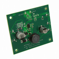
NCP3065SOBCKGEVB
Description
EVAL BOARD FOR NCP3065SOBCKG
Manufacturer
ON Semiconductor
Datasheets
1.NCP3065DR2G.pdf
(18 pages)
2.NCP30653ABCKGEVB.pdf
(18 pages)
3.NCP3065SOBCKGEVB.pdf
(1 pages)
Specifications of NCP3065SOBCKGEVB
Design Resources
NCP3065 Buck Eval Board BOM NCP3065SOBCKGEVB Gerber Files NCP3065 Buck Eval Board Schematic
Current - Output / Channel
350mA
Outputs And Type
1, Non-Isolated
Voltage - Output
3.6V
Voltage - Input
12V
Utilized Ic / Part
NCP3065
Core Chip
NCP3065
Topology
Buck-Boost
Development Tool Type
Hardware - Eval/Demo Board
Leaded Process Compatible
Yes
Mcu Supported Families
NCP3065
Peak Reflow Compatible (260 C)
Yes
Rohs Compliant
Yes
Lead Free Status / RoHS Status
Lead free / RoHS Compliant
Features
-
Lead Free Status / Rohs Status
Lead free / RoHS Compliant
For Use With/related Products
NCP3065SOBCKG
Other names
NCP3065SOBCKGEVBOS


V
V
V
V
I
D
L
f
regions; in the first region, the peak current to the switch is
exceeded tripping the overcurrent protection and causing
the regulated current to drop, Region 2 is where the current
pk(SW)
Table 12. NCP3065 BOOST BILL OF MATERIALS
OUT
IN
F
SWCE
Qty
Line regulation curve in Figure 24 illustrates three distinct
1
2
1
1
1
1
1
1
1
1
1
2
1
95
90
85
80
75
70
6
Boost 4LED 350 mA
Figure 23. Boost Converter Efficiency for 4 or
Reference
C2,C5
R10
8
C1
C3
C4
D1
D2
Q2
R1
R8
R9
U1
L1
6 LEDs and Output Current 350 mA
Output Voltage
Input Voltage
Schottky Diode Forward Voltage
Switch Voltage Drop
Peak Switch Current
Duty Cycle
Inductor Value
Switching Frequency
10
100 mF/50 V, Electrolytic Capacitor
220 mF/50 V, Electrolytic Capacitor
12
Surface mount power inductor
1 A, 40 V Schottky Rectifier
100 nF, Ceramic Capacitor
General purpose transistor
2.2 nF, Ceramic Capacitor
V
IN
Zener Diode, 36 V
DC−DC Controller
Part Description
14
1.2 kW, Resistor
150 mW, 0.5 W
680 mW, $1%
(V)
1k, Resistor
Boost 6LED 350 mA
16
18
20
http://onsemi.com
22
DO3340P−104MLD
EEEVFK1H101P
EEEVFK1H221P
MBRS140LT3G
17
MM3Z36VT1G
BC817−LT1G
NCP3065
Mfg P/N
is flat and represents normal operation, Region 3 occurs
when V
constant current regulation. Region 3 and 1 are included here
for illustrative purposes as this is not a normal mode of
operation.
support 12 V
a bridge rectifier and input filter capacitor. The rectified dc
voltage is
400
390
380
370
360
350
340
330
320
310
300
Figure 9 illustrates the additional circuitry required to
V
INDC
6
Figure 24. Line Regulation for 4 or 6 LEDs and
IN
Boost 4LED 350 mA
+ 2 * V
is greater than V
8
AC
ON Semiconductor
ON Semiconductor
ON Semiconductor
ON Semiconductor
input signal which includes the addition of
10
AC
Panasonic
Panasonic
Output Current 350 mA
Coilcraft
[ 17 V
Mfg
12
V
DC
IN
OUT
14
(V)
Boost 6LED 350 mA
and there is no longer
G, 10x10.2
Package
F, 8x10.2
SOD123
16
SOT23
SOIC8
1206
0805
2010
0805
1206
0805
SMB
18
20
SMD
SMD
SMD
SMD
SMD
SMD
SMD
SMD
SMD
SMD
SMD
SMD
SMD
Mtg
22
Related parts for NCP3065SOBCKGEVB
Image
Part Number
Description
Manufacturer
Datasheet
Request
R

Part Number:
Description:
Up to 1.5 A Constant Current Switching Regulator for LEDs
Manufacturer:
ON Semiconductor
Datasheet:

Part Number:
Description:
EVAL BOARD FOR NCP3065SOBSTG
Manufacturer:
ON Semiconductor
Datasheet:

Part Number:
Description:
EVAL BOARD FOR NCP30653ABCKG
Manufacturer:
ON Semiconductor
Datasheet:
Part Number:
Description:
ON Semiconductor [VOLTAGE REGULATOR]
Manufacturer:
ON Semiconductor
Datasheet:
Part Number:
Description:
357-036-542-201 CARDEDGE 36POS DL .156 BLK LOPRO
Manufacturer:
ON Semiconductor
Datasheet:
Part Number:
Description:
357-036-542-201 CARDEDGE 36POS DL .156 BLK LOPRO
Manufacturer:
ON Semiconductor
Datasheet:
Part Number:
Description:
357-036-542-201 CARDEDGE 36POS DL .156 BLK LOPRO
Manufacturer:
ON Semiconductor
Datasheet:
Part Number:
Description:
357-036-542-201 CARDEDGE 36POS DL .156 BLK LOPRO
Manufacturer:
ON Semiconductor
Datasheet:
Part Number:
Description:
357-036-542-201 CARDEDGE 36POS DL .156 BLK LOPRO
Manufacturer:
ON Semiconductor
Datasheet:
Part Number:
Description:
357-036-542-201 CARDEDGE 36POS DL .156 BLK LOPRO
Manufacturer:
ON Semiconductor
Datasheet:
Part Number:
Description:
357-036-542-201 CARDEDGE 36POS DL .156 BLK LOPRO
Manufacturer:
ON Semiconductor
Datasheet:
Part Number:
Description:
357-036-542-201 CARDEDGE 36POS DL .156 BLK LOPRO
Manufacturer:
ON Semiconductor
Datasheet:
Part Number:
Description:
357-036-542-201 CARDEDGE 36POS DL .156 BLK LOPRO
Manufacturer:
ON Semiconductor
Datasheet:
Part Number:
Description:
357-036-542-201 CARDEDGE 36POS DL .156 BLK LOPRO
Manufacturer:
ON Semiconductor
Datasheet: