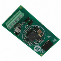
NCP3066DFSEPGEVB ON Semiconductor, NCP3066DFSEPGEVB Datasheet - Page 14

NCP3066DFSEPGEVB
Manufacturer Part Number
NCP3066DFSEPGEVB
Description
EVAL BOARD FOR NCP3066DFSEPG
Manufacturer
ON Semiconductor
Specifications of NCP3066DFSEPGEVB
Design Resources
NCP3066 SEPIC DFN Eval Board BOM NCP3066DFSEPGEVB Gerber Files NCP3066 SEPIC DFN Eval Board Schematic
Current - Output / Channel
350mA, 700mA, or 1.05A
Outputs And Type
1, Non-Isolated
Voltage - Output
7.2V
Features
Adjustable peak current limit
Voltage - Input
24.7VAC or 12 ~ 24 VDC
Utilized Ic / Part
NCP3066
Silicon Manufacturer
On Semiconductor
Silicon Core Number
NCP3066
Kit Application Type
Power Management - Voltage Regulator
Rohs Compliant
Yes
Lead Free Status / RoHS Status
Lead free / RoHS Compliant
For Use With/related Products
NCP3066DFSEPG
Other names
NCP3066DFSEPGEVBOS
Table 4. TEST RESULTS
Line Regulation
Output Ripple
Efficiency
95
90
85
80
75
70
65
60
5
Figure 25. Boost LED Driver Efficiency
Figure 23. Boost Demoboard Layout
7
150 mA 6 LED
(19.2 V)
9
INPUT VOLTAGE (V)
11
150 mA 8 LED
(25.6 V)
13
3.50
2.50
1.50
0.50
Vin = 10 V to 20 V, Vout = 19.2 V, Iout = 350 mA
Vin = 10 V to 20 V, Vout = 19.2 V, Iout = 350 mA
Vin = 12 V, Vout = 19.2 V, Iout = 350 mA
3.0
2.0
1.0
0
0
15
10
Figure 26. Dimming Characteristic
20
17
http://onsemi.com
30
ON/OFF DUTY CYCLE (%)
19
40
14
50
illustrates the basic circuitry in boost topology, which allows
supplying string up to eight LEDs up to 150 mA
consumption. Table 3, Bill of Materials shows the small
number of additional parts which are necessary to assembly
mentioned demoboard. The demoboard based on one layer
PCB and the layout is shown in Figure 23, Buck Demoboard
Layout. The photo of this demoboard is mentioned in
Figure 24, Boost Demoboard Photo. Figure 26, Dimming
Characteristic shows behavior of circuitry in case the square
wave signal with 5 V amplitude and 300 Hz frequency was
delivered into ON/OFF pin of device. There was tested eight
LEDs string with 150 mA consumption and V
room temperature.
Figure 25. Efficiency of Boost LED Driver.
Figure 22, Boost Demoboard Application Schematic,
The efficiency of this demoboard is mentioned in
60
Figure 24. Boost Demonstration Photo
70
80
90
100
25 mA
55 mA
85%
IN
= 10 V at


