IRPLLED1 International Rectifier, IRPLLED1 Datasheet - Page 9
IRPLLED1
Manufacturer Part Number
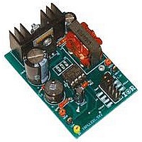
IRPLLED1
Description
BOARD EVALUATION FOR IRS2540PBF
Manufacturer
International Rectifier
Specifications of IRPLLED1
Current - Output / Channel
1.5A
Outputs And Type
1, Non-Isolated
Voltage - Output
24V
Features
Dimmable
Voltage - Input
50 ~ 170V
Utilized Ic / Part
IRS2540PBF
Core Chip
IRS2540, IRS2541, IRS25401
Topology
Buck (Step Down)
No. Of Outputs
1
Output Current
1.5A
Output Voltage
500mV
Dimming Control Type
PWM
Development Tool Type
Hardware - Eval/Demo Board
Lead Free Status / RoHS Status
Contains lead / RoHS compliant by exemption


www.irf.com
EN
HO
LO
Open Circuit Protection Mode
By using the suggested
voltage
capacitor,
diode,
voltage can be clamped
at any desired value. In
open-circuit
without output clamp,
the
terminal will float at the
high-side
Switching
between the HO and LO
outputs, whether due to the
output voltage clamp or the watchdog timer.
Transients and switching will be observed at the
positive output terminal as seen in Fig. 8.
difference in signal shape, between the output
voltage and the I
100
90
80
70
60
50
40
30
20
10
0
0
positive
Fig.5 Light Output vs Enable Pin Duty Cycle
10
the
Fig.6 IRS254(0,1) Dimming Signals
Enable Duty Cycle Relationship to Light Output
and
will
input
20
condition
divider,
FB
output
output
zener
30
still
, is due to the capacitor used to
Percentage of Light Output
voltage.
40
occur
50
60
Vout
Fig.7 Open Circuit
Protection Scheme
70
R1
R2
IFB
EN
80
3
4
90
The
100
form the voltage clamp. The repetition of the spikes
can be reduced by simply increasing the capacitor
size.
The two resistors form a voltage divider for the
output, which is then fed into the cathode of the
zener diode. The diode will only conduct, flooding
the enable pin, when its nominal voltage is
exceeded. The chip will enter a disabled state once
the divider network produces a voltage at least 2.5 V
greater than the zener rating. The capacitor serves
only to filter and slow the transients/switching at the
positive output terminal.
voltage can be determined by the following analysis.
The choice of capacitor is at the designer’s
discretion.
Under-voltage Lock-out Mode
The under-voltage lock-out mode (UVLO) is defined
as the state IRS254(0,1) is in when V
turn-on threshold of the IC.
conditions, if the IC supply remains below V
IRS254(0,1) will enter the UVLO mode. This state is
very similar to when the IC has been disabled via
control signals, except that LO is also held low.
When the supply is increased to
the normal operation mode.
V
DZ
Fig.8 Open Circuit Fault Signals, with Clamp
out
=
=
Zener
(
2
5 .
V
Diode
IRS254(0,1)(S)PbF
+
DZ
R
2
)(
Nominal
R
1
+
R
The clamped output
2
If already in normal
)
Rated
V
CCUV+
During startup
CC
, the IC enters
Voltage
Page 9
is below the
CCUV+
, the
Related parts for IRPLLED1
Image
Part Number
Description
Manufacturer
Datasheet
Request
R

Part Number:
Description:
SCHOTTKY RECTIFIER
Manufacturer:
International Rectifier Corp.
Datasheet:
Part Number:
Description:
SCHOTTKY RECTIFIER
Manufacturer:
International Rectifier Corp.
Datasheet:
Part Number:
Description:
SCHOTTKY RECTIFIER
Manufacturer:
International Rectifier Corp.
Datasheet:
Part Number:
Description:
SCHOTTKY RECTIFIER
Manufacturer:
International Rectifier Corp.
Datasheet:
Part Number:
Description:
SCHOTTKY RECTIFIER
Manufacturer:
International Rectifier Corp.
Datasheet:
Part Number:
Description:
SCHOTTKY RECTIFIER
Manufacturer:
International Rectifier Corp.
Datasheet:
Part Number:
Description:
SCHOTTKY RECTIFIER
Manufacturer:
International Rectifier Corp.
Datasheet:
Part Number:
Description:
SCHOTTKY RECTIFIER
Manufacturer:
International Rectifier Corp.
Datasheet:
Part Number:
Description:
SCHOTTKY RECTIFIER
Manufacturer:
International Rectifier Corp.
Datasheet:
Part Number:
Description:
SCHOTTKY RECTIFIER
Manufacturer:
International Rectifier Corp.
Datasheet:
Part Number:
Description:
SCHOTTKY RECTIFIER
Manufacturer:
International Rectifier Corp.
Datasheet:
Part Number:
Description:
SCHOTTKY RECTIFIER
Manufacturer:
International Rectifier Corp.
Datasheet:
Part Number:
Description:
SCHOTTKY RECTIFIER
Manufacturer:
International Rectifier Corp.
Datasheet:
Part Number:
Description:
SCHOTTKY RECTIFIER
Manufacturer:
International Rectifier Corp.
Datasheet:
Part Number:
Description:
SCHOTTKY RECTIFIER
Manufacturer:
International Rectifier Corp.
Datasheet: