LP5526TLEV National Semiconductor, LP5526TLEV Datasheet - Page 12
LP5526TLEV
Manufacturer Part Number
LP5526TLEV
Description
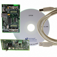
BOARD EVAL LP5526 LMU LED DRIVER
Manufacturer
National Semiconductor
Series
PowerWise®r
Specifications of LP5526TLEV
Current - Output / Channel
150mA
Outputs And Type
2 (25mA), 1 (150mA)
Voltage - Output
20 V
Features
Camera Flash, Dimmable, RGB Controller
Voltage - Input
3 ~ 5.5V
Utilized Ic / Part
LP5526
Lead Free Status / RoHS Status
Not applicable / Not applicable


www.national.com
Overlapping Mode
In overlapping mode the brightness is controlled using PWM
duty cycle based control method as the following figure
shows.
Since RGB outputs are on simultaneously, the maximum load
peak current is:
Non-Overlapping Mode
The timing diagram shows the split R, G and B and brightness
control effect to split parts. Full brightness is used in the dia-
The non-overlapping mode has 16 programmed colors (dif-
ferent R, G and B ratio -> different color). Since the R, G and
B are split into non-overlapping slots the output current
through the RGB LED can be calculated with following equa-
tion:
where
C = Color [%] (see table of color control)
B = Brightness [%] (see table of brightness control)
2. LED ON/OFF CONTROL WITH RGB CONTROL
REGISTER
Each LED output can be set ON by writing the corresponding
bit high in the Control register (00H). RSW controls RLED,
GSW controls GLED and BSW controls BLED output. Note
that EN_RGB bit must be high and RGB_PWM bit low. In this
mode, the RGB register (01H) does not have any effect.
CC_SW bit in Control register defines the LED output mode.
I
AVG
=(C
R
×I
R
+C
G
×I
G
+C
B
×I
B
)×B
Non-Overlapping Mode
Overlapping Mode
12
gram. If for example ½ brightness is used, the frame is still
50µs, but all LED outputs’ ON time is 50% shorter and at the
last 25µs all LED outputs are OFF.
Switch Mode / Constant Current Mode
Each RGB LED output can be set to act as a switch or a con-
stant current sink. Selection of mode is done with the CC_SW
bit in the Control Register. If bit is set high, then the switch
mode is selected. Default is switch mode.
SWITCH MODE
In switch mode, the RGB LED outputs are low ohmic switches
to ground. Resistance is typically 3.2Ω. External ballast re-
sistors must be used to limit the current through the LED.
CONSTANT CURRENT MODE
In constant current mode, the maximum output current is de-
fined with a single external resistor (R
current control register (address 02H).
IG[1:0]
IR[1:0]
IB[1:0]
Name
I
MAX
RGB MAX CURRENT REGISTER (02H)
= I(RLED)
5:4
3:2
1:0
Bit
MAX
+ I(GLED)
RLED maximum current
GLED maximum current
BLED maximum current
Description
MAX
RGB
+ I(BLED)
) and the maximum
20179787
20179788
MAX
Related parts for LP5526TLEV
Image
Part Number
Description
Manufacturer
Datasheet
Request
R

Part Number:
Description:
National Semiconductor [8-Bit D/A Converter]
Manufacturer:
National Semiconductor
Datasheet:
Part Number:
Description:
National Semiconductor [Media Coprocessor]
Manufacturer:
National Semiconductor
Datasheet:
Part Number:
Description:
Digitally Controlled Tone and Volume Circuit with Stereo Audio Power Amplifier, Microphone Preamp Stage and National 3D Sound
Manufacturer:
National Semiconductor
Datasheet:
Part Number:
Description:
Digitally Controlled Tone and Volume Circuit with Stereo Audio Power Amplifier, Microphone Preamp Stage and National 3D Sound
Manufacturer:
National Semiconductor
Datasheet:
Part Number:
Description:
AC97 Rev 2 Codec with Sample Rate Conversion and National 3D Sound
Manufacturer:
National Semiconductor
Part Number:
Description:
Manufacturer:
National Semiconductor
Datasheet:
Part Number:
Description:
Manufacturer:
National Semiconductor
Datasheet:
Part Number:
Description:
General Purpose, Low Voltage, Low Power, Rail-to-Rail Output Operational Amplifiers
Manufacturer:
National Semiconductor
Datasheet:
Part Number:
Description:
8-bit 20 MSPS flash A/D converter.
Manufacturer:
National Semiconductor
Datasheet:
Part Number:
Description:
Low Noise Quad Operational Amplifier
Manufacturer:
National Semiconductor
Datasheet:
Part Number:
Description:
Quad Differential Line Receivers
Manufacturer:
National Semiconductor
Datasheet:
Part Number:
Description:
Quad High Speed Trapezoidal? Bus Transceiver
Manufacturer:
National Semiconductor
Datasheet:
Part Number:
Description:
Dual Line Receiver
Manufacturer:
National Semiconductor
Datasheet:
Part Number:
Description:
TTL to 10k ECL Level Translator with Latch
Manufacturer:
National Semiconductor
Datasheet: