LP5526TLEV National Semiconductor, LP5526TLEV Datasheet - Page 21
LP5526TLEV
Manufacturer Part Number
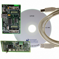
LP5526TLEV
Description
BOARD EVAL LP5526 LMU LED DRIVER
Manufacturer
National Semiconductor
Series
PowerWise®r
Specifications of LP5526TLEV
Current - Output / Channel
150mA
Outputs And Type
2 (25mA), 1 (150mA)
Voltage - Output
20 V
Features
Camera Flash, Dimmable, RGB Controller
Voltage - Input
3 ~ 5.5V
Utilized Ic / Part
LP5526
Lead Free Status / RoHS Status
Not applicable / Not applicable


LOGIC INPUT SCL, SDA, GPIO[0:2]
V
V
I
f
LOGIC INPUT NRST
V
V
I
t
LOGIC OUTPUT SDA
V
V
I
LOGIC OUTPUT GPIO[0:2]
V
V
I
I
SCL
I
NRST
L
L
IL
IH
IL
IH
OL
OH
OL
OH
General Purpose I/O Functionality
LP5526 has three general purpose I/O pins: GPIO[0]/PWM,
GPIO[1] and GPIO[2]. GPIO[0]/PWM can also be used as a
PWM input for the external LED PWM controlling. GPIO bi-
directional drivers are operating from the V
main.
Registers for GPIO are as follows:
Logic Interface Characteristics
(V
DDIO
Symbol
EN_PWM_PIN
= 1.65V...V
OEN[2:0]
Name
Input Low Level
Input High Level
Logic Input Current
Clock Frequency
Input Low Level
Input High Level
Input Current
Reset Pulse Width
Output Low Level
Output High Level
Output Leakage Current
Output Low Level
Output High Level
Output Leakage Current
DD1,2
GPIO CONTROL (06H)
unless otherwise noted)
Parameter
Bit
2:0
4
Enable PWM pin
0 = disable
1 = enable
GPIO pin direction
0 = input
1 = output
Description
DDIO
I
I
V
I
I
V
SDA
SDA
GPIO
GPIO
SDA
GPIO
supply do-
= 3mA
= -3mA
= 2 mA
= -2 mA
= 2.8V
= 2.8V
Conditions
21
GPIO control register is used to set the direction of each GPIO
pin. For example, by setting OEN0 bit high the GPIO[0]/PWM
pin acts as a logic output pin with data defined DATA0 in GPIO
data register. Note, that the EN_PWM_PIN bit overrides
OEN0 state by forcing GPIO[0]/PWM to act as PWM input.
GPIO[1] and GPIO[2] pins can be selected to be inputs or
outputs, defined by OEN1 and OEN2 bit status. PWM func-
tionality is valid only for GPIO[0]/PWM pin. GPIO data register
contains the data of GPIO pins. When output direction is se-
lected to GPIO pin, then GPIO data register defines the output
pin state. When GPIO data register is read, it contains the
state of the pin despite of the pin direction.
DATA[2:0]
Name
0.8×V
V
V
−1.0
DDIO
DDIO
Min
-1.0
0.5
1.2
0.5
10
GPIO DATA (07H)
DDIO
−
−
Bit
2:0
V
V
DDIO
DDIO
Typ
0.3
0.3
0.3
0.3
Data bits
−
−
0.2×V
Description
Max
400
0.5
1.0
0.5
1.0
0.5
1.0
1.0
DDIO
www.national.com
Units
kHz
µA
µA
µA
µA
µs
V
V
V
V
V
V
V
Related parts for LP5526TLEV
Image
Part Number
Description
Manufacturer
Datasheet
Request
R

Part Number:
Description:
National Semiconductor [8-Bit D/A Converter]
Manufacturer:
National Semiconductor
Datasheet:
Part Number:
Description:
National Semiconductor [Media Coprocessor]
Manufacturer:
National Semiconductor
Datasheet:
Part Number:
Description:
Digitally Controlled Tone and Volume Circuit with Stereo Audio Power Amplifier, Microphone Preamp Stage and National 3D Sound
Manufacturer:
National Semiconductor
Datasheet:
Part Number:
Description:
Digitally Controlled Tone and Volume Circuit with Stereo Audio Power Amplifier, Microphone Preamp Stage and National 3D Sound
Manufacturer:
National Semiconductor
Datasheet:
Part Number:
Description:
AC97 Rev 2 Codec with Sample Rate Conversion and National 3D Sound
Manufacturer:
National Semiconductor
Part Number:
Description:
Manufacturer:
National Semiconductor
Datasheet:
Part Number:
Description:
Manufacturer:
National Semiconductor
Datasheet:
Part Number:
Description:
General Purpose, Low Voltage, Low Power, Rail-to-Rail Output Operational Amplifiers
Manufacturer:
National Semiconductor
Datasheet:
Part Number:
Description:
8-bit 20 MSPS flash A/D converter.
Manufacturer:
National Semiconductor
Datasheet:
Part Number:
Description:
Low Noise Quad Operational Amplifier
Manufacturer:
National Semiconductor
Datasheet:
Part Number:
Description:
Quad Differential Line Receivers
Manufacturer:
National Semiconductor
Datasheet:
Part Number:
Description:
Quad High Speed Trapezoidal? Bus Transceiver
Manufacturer:
National Semiconductor
Datasheet:
Part Number:
Description:
Dual Line Receiver
Manufacturer:
National Semiconductor
Datasheet:
Part Number:
Description:
TTL to 10k ECL Level Translator with Latch
Manufacturer:
National Semiconductor
Datasheet: