NCP102MBGEVB ON Semiconductor, NCP102MBGEVB Datasheet - Page 8
NCP102MBGEVB
Manufacturer Part Number
NCP102MBGEVB
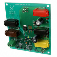
Description
EVAL BOARD FOR NCP102MBG
Manufacturer
ON Semiconductor
Specifications of NCP102MBGEVB
Design Resources
NCP102 Demo Brd BOM NCP102MBGEVB Gerber Files NCP102 EVB Schematic
Channels Per Ic
1 - Single
Voltage - Output
1.2V
Current - Output
3A
Voltage - Input
1.8V
Regulator Type
Positive Fixed
Board Type
Fully Populated
Utilized Ic / Part
NCP102
Lead Free Status / RoHS Status
Lead free / RoHS Compliant
Operating Temperature
-
Lead Free Status / Rohs Status
Lead free / RoHS Compliant
For Use With/related Products
NCP102MBG
Other names
NCP102MBGEVBOS


SOFT-START
output voltage. The adjustable soft-start built into the
NCP102 allows the user to select the optimum soft-start
time for the application. The soft-start time is set with a
capacitor from the SOFT-S pin to ground.
voltage based on the slope of the soft-start capacitor voltage,
C
4.5 mA (typ.) current source, I
charge of the soft-start capacitor and thus the output voltage.
The soft-start period, t
voltage reaches 0.8 V (typ). The soft-start capacitor is
calculated using Equation 3.
V
disabled using the EN pin.
POWER SEQUENCING
SOFT-S and EN pins. This is achieved by directly
connecting the SOFT-S pin of the master controller to the
EN pin of the slave controller. If V
resistor divider is required to limit the voltage on the EN pin
because the pin is internally clamped to 9.5 V. Figure 13
shows the timing waveforms of the master and slave
controllers.
ENABLE
SOFT-S
CC
Soft-start reduces inrush current and overshoot of the
Soft-start is achieved by controlling the slope of the DRV
The soft-start capacitor is internally pulled to GND when
Power sequencing can be easily implemented using the
J5
is not within its operating range or the controller is
100 p
. The capacitor is charged to V
C11
R8
1 k
t
SOFT*S
MMBT3904
10 k
R6
Q3
+
SOFT-S
c
TP1
SOFT-S
SOFT*S
TP3
I
365 k
R7
SOFT*S
, ends once the capacitor
@ 0.8
. This results in a linear
CC
1
2
3
CC
is above 9.5 V a
EN
GND
FB
with a constant
NCP102
Figure 14. Circuit Schematic
U1
SOFT-S
DRV
V
http://onsemi.com
(eq. 3)
CC
TP4
0.01
C1
NCP102
6
5
4
V
CC
8
0.01
C3
J1
TP5
calculated using Equation 3 because the soft-start capacitor
charge current is now increased by the enable charge current.
The soft-start time is calculated using Equation 3 by
replacing I
APPLICATION INFORMATION
demonstration board and an application note to facilitate
design using the NCP102 and to reduce development cycle
time. All the tools can be downloaded at www.onsemi.com.
determine most of the system parameters of a linear
regulator. The tool also evaluates the frequency response of
the system. The demonstration board is designed to generate
a 1.2 V/3 A voltage supply from a 1.8 V supply. The circuit
schematic is shown in Figure 14 and the regulator design is
described in Application Note AND8303.
100 p
Power sequencing will affect the soft-start time
ON Semiconductor provides an electronic design tool, a
The electronic design tool allows the user to easily
R5
0
200
C4
R1
Figure 13. Power-up Sequencing Waveforms
TP12
NTD40N03
SOFT-S
Q1
R2
R3
V
with the sum of I
in
100
10 k
R4
20 k
Soft-Start (master)
V
J2
out
TP6a
TP7
Open
(master)
Q2
1000
Soft-Start (slave)
C10
470
C7
V
EN
out
(slave)
and I
4.7
4.7
C8
C5
SOFT-S
TP2a
C9
0.1
C6
0.1
J4
J6
.
TP8
TP9
TP10
TP11
TP2
GND
V
J3
TP6
out
Related parts for NCP102MBGEVB
Image
Part Number
Description
Manufacturer
Datasheet
Request
R

Part Number:
Description:
ON Semiconductor [VOLTAGE REGULATOR]
Manufacturer:
ON Semiconductor
Datasheet:
Part Number:
Description:
357-036-542-201 CARDEDGE 36POS DL .156 BLK LOPRO
Manufacturer:
ON Semiconductor
Datasheet:
Part Number:
Description:
357-036-542-201 CARDEDGE 36POS DL .156 BLK LOPRO
Manufacturer:
ON Semiconductor
Datasheet:
Part Number:
Description:
357-036-542-201 CARDEDGE 36POS DL .156 BLK LOPRO
Manufacturer:
ON Semiconductor
Datasheet:
Part Number:
Description:
357-036-542-201 CARDEDGE 36POS DL .156 BLK LOPRO
Manufacturer:
ON Semiconductor
Datasheet:
Part Number:
Description:
357-036-542-201 CARDEDGE 36POS DL .156 BLK LOPRO
Manufacturer:
ON Semiconductor
Datasheet:
Part Number:
Description:
357-036-542-201 CARDEDGE 36POS DL .156 BLK LOPRO
Manufacturer:
ON Semiconductor
Datasheet:
Part Number:
Description:
357-036-542-201 CARDEDGE 36POS DL .156 BLK LOPRO
Manufacturer:
ON Semiconductor
Datasheet:
Part Number:
Description:
357-036-542-201 CARDEDGE 36POS DL .156 BLK LOPRO
Manufacturer:
ON Semiconductor
Datasheet:
Part Number:
Description:
357-036-542-201 CARDEDGE 36POS DL .156 BLK LOPRO
Manufacturer:
ON Semiconductor
Datasheet:
Part Number:
Description:
357-036-542-201 CARDEDGE 36POS DL .156 BLK LOPRO
Manufacturer:
ON Semiconductor
Datasheet:
Part Number:
Description:
Manufacturer:
ON Semiconductor
Datasheet:
Part Number:
Description:
Manufacturer:
ON Semiconductor
Datasheet:
Part Number:
Description:
Manufacturer:
ON Semiconductor
Datasheet: