MCP1726EV Microchip Technology, MCP1726EV Datasheet
MCP1726EV
Specifications of MCP1726EV
Available stocks


Related parts for MCP1726EV

MCP1726EV Summary of contents
Page 1
... Microchip Technology Inc. MCP1726 Evaluation Board User’s Guide DS51550B ...
Page 2
... Select Mode, Smart Serial, SmartTel, Total Endurance, UNI/O, WiperLock and ZENA are trademarks of Microchip Technology Incorporated in the U.S.A. and other countries. SQTP is a service mark of Microchip Technology Incorporated in the U.S.A. All other trademarks mentioned herein are property of their respective companies. ...
Page 3
... Appendix A. Schematics and Layouts ...................................................................... 13 A.1 Introduction .................................................................................................. 13 A.2 Board Schematic A.3 Board - Outline A.4 Board - Top Layer A.5 Board - Bottom Layer Appendix B. Bill Of Materials (BOM) ......................................................................... 19 Worldwide Sales and Service .................................................................................... 20 © 2006 Microchip Technology Inc. MCP1726 EVALUATION BOARD Table of Contents ...................................................................................... 14 ......................................................................................... 15 .................................................................................... 16 ............................................................................... 17 USER’S GUIDE ...
Page 4
... NOTES: DS51550B-page iv © 2006 Microchip Technology Inc. ...
Page 5
... Appendix A. “Schematics and Layouts” – Shows the schematic and layout diagrams for the MCP1726 Evaluation Board. • Appendix B. “Bill Of Materials (BOM)” – Lists the parts used to build the MCP1726 Evaluation Board. © 2006 Microchip Technology Inc. MCP1726 EVALUATION BOARD USER’S GUIDE Preface ...
Page 6
... Optional arguments mcc18 [options] file [options] Choice of mutually exclusive errorlevel {0|1} arguments selection Replaces repeated text var_name [, var_name...] Represents code supplied by void main (void) user { ... } © 2006 Microchip Technology Inc. Examples ® IDE User’s Guide ...
Page 7
... Technical support is available through the web site at: http://support.microchip.com DOCUMENT REVISION HISTORY Revision B (August 2006) • Add disclaimer to Bill of Materials regarding RoHS-Compliant part numbers. Revision A (April 2005 • Initial Release of this Document. © 2006 Microchip Technology Inc. DS51550B-page 3 ...
Page 8
... NOTES: DS51550B-page 4 © 2006 Microchip Technology Inc. ...
Page 9
... IN1 +V IN1 µ kΩ PGND PGND SHDN1 PGND +V IN2 +V IN2 C 1 4.7 µ kΩ PGND PGND SHDN1 PGND FIGURE 1-1: MCP1726 Evaluation Board Schematic. © 2006 Microchip Technology Inc. MCP1726 EVALUATION BOARD USER’S GUIDE OUT ADJ JP4 SHDN DELAY GND PWRGD 100 kΩ ...
Page 10
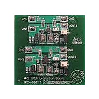
... WHAT THE MCP1726 1A LDO EVALUATION BOARD KIT INCLUDES This MCP1726 1A LDO Evaluation Board Kit includes: • The MCP1726 1A LDO Evaluation Board • Analog and Interface Products Demonstration Boards CD-ROM (DS21912) - MCP1726 1A LDO Evaluation Board User’s Guide (DS51550) DS51550B-page 6 © 2006 Microchip Technology Inc. ...
Page 11
... All of the connections to the MCP1726 Evaluation Board are made through surface-mount test points. These test points can be removed with a soldering iron if you wish to solder wires directly to the pads that are provided on the board. © 2006 Microchip Technology Inc. MCP1726 EVALUATION BOARD USER’S GUIDE ...
Page 12
... The potentiometer will allow you to adjust the output voltage over the full range of 0.8V to 5.0V. If you would like to use fixed resistor values to set the output voltage of the LDO, the potentiometer can be removed and the pads for the potentiometer can be used to solder your fixed value resistors into the circuit. DS51550B-page 8 © 2006 Microchip Technology Inc. ...
Page 13
... JP4 should be populated (use the additional black jumper top that is provided). This will connect pin the VOUT1 output (for the fixed-output voltage devices, pins 7 and 8 of the MCP1726 are both V proper operation. © 2006 Microchip Technology Inc. pin on the DELAY pin capacitor. This gives a ...
Page 14
... The potentiometer will allow you to adjust the output voltage over the full range of 0.8V to 5.0V. If you would like to use fixed resistor values to set the output voltage of the LDO, the potentiometer can be removed and the pads for the potentiometer can be used to solder your fixed-value resistors into the circuit. DS51550B-page 10 © 2006 Microchip Technology Inc. ...
Page 15
... JP1 should be populated (use the additional black jumper top that is provided). This will connect pin the VOUT2 output (for the fixed-output voltage devices, pins 7 and 8 of the MCP1726 are both V proper operation. © 2006 Microchip Technology Inc. pin on the DELAY pin capacitor. This gives a ...
Page 16
... NOTES: DS51550B-page 12 © 2006 Microchip Technology Inc. ...
Page 17
... This appendix contains the following schematics and layouts for the MCP1726 Evaluation Board. • Board Schematic • Board Outline • Board – Top Layer • Board – Bottom Layer © 2006 Microchip Technology Inc. MCP1726 EVALUATION BOARD USER’S GUIDE DS51550B-page 13 ...
Page 18
... A.2 BOARD SCHEMATIC DS51550B-page 14 © 2006 Microchip Technology Inc. ...
Page 19
... A.3 BOARD - OUTLINE © 2006 Microchip Technology Inc. DS51550B-page 15 ...
Page 20
... A.4 BOARD - TOP LAYER DS51550B-page 16 © 2006 Microchip Technology Inc. ...
Page 21
... A.5 BOARD - BOTTOM LAYER © 2006 Microchip Technology Inc. DS51550B-page 17 ...
Page 22
... NOTES: DS51550B-page 18 © 2006 Microchip Technology Inc. ...
Page 23
... Low Quiescent Current LDO, Adjust- able Output, 3X3 DFN Package Note 1: The components listed in this Bill of Materials are representative of the PCB assembly. The released BOM used in manufacturing uses all RoHS-compliant components. © 2006 Microchip Technology Inc. MCP1726 EVALUATION BOARD USER’S GUIDE Description Manufacturer ...
Page 24
... Fax: 886-3-572-6459 Taiwan - Kaohsiung Tel: 886-7-536-4818 Fax: 886-7-536-4803 Taiwan - Taipei Tel: 886-2-2500-6610 Fax: 886-2-2508-0102 Thailand - Bangkok Tel: 66-2-694-1351 Fax: 66-2-694-1350 © 2006 Microchip Technology Inc. EUROPE Austria - Wels Tel: 43-7242-2244-3910 Fax: 43-7242-2244-393 Denmark - Copenhagen Tel: 45-4450-2828 Fax: 45-4485-2829 France - Paris Tel: 33-1-69-53-63-20 ...