MCP1726EV Microchip Technology, MCP1726EV Datasheet - Page 14
MCP1726EV
Manufacturer Part Number
MCP1726EV
Description
BOARD EVAL FOR MCP1726
Manufacturer
Microchip Technology
Datasheets
1.MCP1726EV.pdf
(2 pages)
2.MCP1726EV.pdf
(30 pages)
3.MCP1726EV.pdf
(24 pages)
4.MCP1726EV.pdf
(4 pages)
5.MCP1726EV.pdf
(24 pages)
Specifications of MCP1726EV
Channels Per Ic
1 - Single
Voltage - Output
0.8 ~ 5V
Current - Output
1A
Voltage - Input
2.3 ~ 6V
Regulator Type
Positive Adjustable
Operating Temperature
-40°C ~ 125°C
Board Type
Fully Populated
Utilized Ic / Part
MCP1726
Processor To Be Evaluated
MCP1726
Silicon Manufacturer
Microchip
Silicon Core Number
MCP1726
Kit Application Type
Power Management - Voltage Regulator
Application Sub Type
LDO
Kit Contents
Board Cables CD Docs
Rohs Compliant
Yes
Lead Free Status / RoHS Status
Contains lead / RoHS non-compliant
Lead Free Status / RoHS Status
Lead free / RoHS Compliant, Contains lead / RoHS non-compliant
Available stocks
Company
Part Number
Manufacturer
Quantity
Price
Company:

Part Number:
MCP1726EV
Manufacturer:
Microchip Technology
Quantity:
135


2.5
DS51550B-page 10
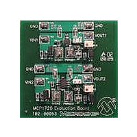
TESTING CIRCUIT 2 OF THE MCP1726 EVALUATION BOARD
2.5.1
Powering the MCP1726 Evaluation Board
Apply the input voltage to test points TP1 (VIN2) and TP2 (GND). Connect the
positive-side of the input source (+) to test point TP1 (VIN2). Connect the negative, or
return, side (–) of the input source to the test point TP2 (GND). These two test points
are located on the lower-left side of the board. The power supply input voltage must be
in the specified operating range for the board to operate correctly. The UVLO feature
of the MCP1726 prevents the device from operating when the input voltage is too low
(see data sheet for UVLO thresholds).
When input voltage is applied and is above the input UVLO threshold, the LDO output
will turn on automatically. The SHDN2 input has been pulled up to VIN2 which turns the
device on. The LDO output can be turned off by pulling the SHDN2 input (TP3) low
(short SHDN2 to GND).
When input voltage is applied, the red portion of the D1 LED will illuminate. As long as
input voltage is present, the red portion of this LED will be on.
Applying the load to the MCP1726 Evaluation Board
To apply a load to VOUT2 of the MCP1726 Evaluation Board, the positive-side of the
load (+) should be connected to test point TP6 (VOUT2). The negative-side of the load
(–) should be connected to test point TP4 (GND).
The maximum output current of the MCP1726 is 1.0A. If the output load exceeds this
level, the MCP1726 will go into current limit at 1.7A. If, during the overload condition,
the device junction temperature exceeds the overtemperature limit of 150°C, the output
of the LDO will turn off and wait for the junction temperature to cool down before turning
the LDO output back on. Circuit 2 of the MCP1726 Evaluation Board evaluates the
SOIC package. When operating at room ambient, this circuit will go into
overtemperature shutdown when the power dissipation in the device reaches about
1.3W.
2.5.2
The MCP1726 Evaluation Board comes with the output voltage preset to 2.5V. To
adjust the output voltage (VOUT2) of circuit 2, the potentiometer (R2) is used. R2 is a
top-side adjust potentiometer. If the desired output voltage is higher than 2.5V, raise the
input voltage to a level that is higher than your desired output voltage. Use a small flat
head screw driver to adjust the R2 potentiometer and monitor the VOUT2 (TP6)
voltage. If your desired output voltage is less than 2.5V, the input voltage of the LDO
must be set to a minimum of 2.3V, as this is the minimum input voltage of the LDO. The
output voltage of the LDO can then be adjusted using the R2 potentiometer.
The potentiometer will allow you to adjust the output voltage over the full range of 0.8V
to 5.0V. If you would like to use fixed resistor values to set the output voltage of the
LDO, the potentiometer can be removed and the pads for the potentiometer can be
used to solder your fixed-value resistors into the circuit.
Power Input and Output Connections
Adjusting the Output Voltage of the LDO
© 2006 Microchip Technology Inc.
Related parts for MCP1726EV
Image
Part Number
Description
Manufacturer
Datasheet
Request
R

Part Number:
Description:
Manufacturer:
Microchip Technology Inc.
Datasheet:
Part Number:
Description:
Manufacturer:
Microchip Technology Inc.
Datasheet:
Part Number:
Description:
Manufacturer:
Microchip Technology Inc.
Datasheet:
Part Number:
Description:
Manufacturer:
Microchip Technology Inc.
Datasheet:
Part Number:
Description:
Manufacturer:
Microchip Technology Inc.
Datasheet:
Part Number:
Description:
Manufacturer:
Microchip Technology Inc.
Datasheet:
Part Number:
Description:
Manufacturer:
Microchip Technology Inc.
Datasheet:
Part Number:
Description:
Manufacturer:
Microchip Technology Inc.
Datasheet: