AD8260-EVALZ Analog Devices Inc, AD8260-EVALZ Datasheet - Page 7
AD8260-EVALZ
Manufacturer Part Number
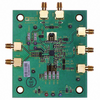
AD8260-EVALZ
Description
BOARD EVAL FOR AD8260
Manufacturer
Analog Devices Inc
Specifications of AD8260-EVALZ
Channels Per Ic
1 - Single
Amplifier Type
Variable Gain
Output Type
Differential
Slew Rate
730 V/µs
-3db Bandwidth
195MHz
Current - Output / Channel
310mA
Operating Temperature
-40°C ~ 105°C
Current - Supply (main Ic)
28.3mA
Voltage - Supply, Single/dual (±)
3.3 V ~ 10 V, ±3.3 V ~ 5 V
Board Type
Fully Populated
Utilized Ic / Part
AD8260
Silicon Manufacturer
Analog Devices
Application Sub Type
Programmable Gain Amplifier
Kit Application Type
Amplifier
Silicon Core Number
AD8260
Kit Contents
Board
Lead Free Status / RoHS Status
Lead free / RoHS Compliant
Lead Free Status / RoHS Status
Lead free / RoHS Compliant, Lead free / RoHS Compliant


PIN CONFIGURATION AND FUNCTION DESCRIPTIONS
Table 3. Pin Function Descriptions
Pin No.
1, 19
2
3
4
5
6
7
8
9, 16
10, 20
11
12
13
14
15
17
18
21, 22
23, 24
25, 26
27
28
29
30
31
32
1
Pins with the same name are connected internally.
1
1
1
1
1
1
Mnemonic
VMDO
TXEN
VMDI
VNCM
VPSB
ENBL
VGAP
VGAN
VNGR
VPSR
GNS3
GNS2
GNS1
GNS0
PRAO
FDBK
PRAI
VPOS
TXOP
VNEG
TXFB
INPN
INRN
INRP
INPP
VOCM
EPAD
NOTES
1. THE EXPOSED PAD IS NOT CONNECTED INTERNALLY. FOR INCREASED RELIABILITY OF THE SOLDER JOINTS
AND MAXIMUM THERMAL CAPABILITY, IT IS RECOMMENDED THAT THE PAD BE SOLDERED TO THE GROUND PLANE.
THE GROUND PLANE PATTERN SHOULD INCLUDE A PATTERN OF VIAS TO INNER LAYERS.
Description
VMID Buffer Output. Requires robust ac decoupling with a capacitance of 0.1 µF capacitor or greater.
Driver Enable. Logic threshold = 1.1 V with ±0.2 V hysteresis.
VMID Input Voltage. Normally decoupled with a 0.1 µF capacitor. When pulled to VNCM, the VMID buffer shuts
down. This can be useful when using the part with dual supplies or when an external midpoint generator is used.
Negative Supply for Bias Cell, VMID Cell, and Logic Inputs. (Ground this pin in applications.)
Positive Supply for Bias Cell and VMID Cell.
Enable. Logic threshold = 1.1 V. When low, the AD8260 is disabled and the supply current is 35 µA when TXEN
and all GNSx pins are also low.
Positive VGA Output (Needs to Be Ac-Coupled for Single Supply).
Negative VGA Output (Needs to Be Ac-Coupled for Single Supply).
Negative Supply for Preamplifier and DGA (Set to −VPOS for Dual Supply; GND for Single Supply).
Positive Supply for Preamplifier, DGA, and GNSx Logic Decoder.
MSB for Gain Control. Logic threshold = 1.1 V.
Gain Control Bit. Logic threshold = 1.1 V.
Gain Control Bit. Logic threshold = 1.1 V.
LSB for Gain Control. Logic threshold = 1.1 V.
Preamplifier Output.
Negative Input of Preamplifier.
Positive Input of Preamplifier.
Positive Supply for Driver Amplifier.
Driver Output.
Negative Supply for Driver Amplifier (Set to −VPOS for Dual Supply; GND for Single Supply).
Feedback for Driver Amplifier.
Negative Driver Amplifier Input.
Negative Gain Resistor Input for Driver Amplifier.
Positive Gain Resistor Input for Driver Amplifier.
Positive Driver Amplifier Input.
Output Common Mode Pin. Normally connected to Pin VMDO.
Exposed Pad. The exposed pad is not connected internally. For increased reliability of the solder joints and
maximum thermal capability it is recommended that the pad be soldered to the ground plane. The ground plane
pattern should include a pattern of vias to inner layers.
VMDO
VNCM
VGAP
VGAN
TXEN
VPSB
ENBL
VMDI
1
2
3
4
5
6
7
8
Figure 2. Pin Configuration
32
9
Rev. A | Page 7 of 32
10
31
(Not to Scale)
PIN 1
INDICATOR
11
30
AD8260
TOP VIEW
29
12
13
28
14
27
15 16
26
25
24
23
22
21
20
19
18
17
TXOP
TXOP
VPOS
VPOS
VPSR
VMDO
PRAI
FDBK
AD8260
Related parts for AD8260-EVALZ
Image
Part Number
Description
Manufacturer
Datasheet
Request
R

Part Number:
Description:
High Speed, Low Power Dual Operational Amplifier
Manufacturer:
Analog Devices
Datasheet:

Part Number:
Description:
±1.7g Dual-Axis IMEMS Accelerometer Evaluation Board
Manufacturer:
Analog Devices Inc
Datasheet:

Part Number:
Description:
Inertial Sensor Evaluation System
Manufacturer:
Analog Devices Inc
Datasheet:
Part Number:
Description:
Manufacturer:
Analog Devices Inc
Datasheet:
Part Number:
Description:
Manufacturer:
Analog Devices Inc
Datasheet:
Part Number:
Description:
Manufacturer:
Analog Devices Inc
Datasheet:
Part Number:
Description:
Manufacturer:
Analog Devices Inc
Datasheet:
Part Number:
Description:
Manufacturer:
Analog Devices Inc
Datasheet:
Part Number:
Description:
Manufacturer:
Analog Devices Inc
Datasheet:
Part Number:
Description:
Manufacturer:
Analog Devices Inc
Datasheet:
Part Number:
Description:
Manufacturer:
Analog Devices Inc
Datasheet:
Part Number:
Description:
Manufacturer:
Analog Devices Inc
Datasheet:
Part Number:
Description:
Manufacturer:
Analog Devices Inc
Datasheet: