EK16 Cirrus Logic Inc, EK16 Datasheet - Page 4
EK16
Manufacturer Part Number
EK16
Description
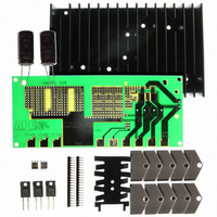
KIT EVAL PA90,91,92,93,98 PINOUT
Manufacturer
Cirrus Logic Inc
Series
Apex Precision Power™r
Datasheets
1.EK16.pdf
(5 pages)
2.EK16.pdf
(6 pages)
3.EK16.pdf
(6 pages)
4.EK16.pdf
(7 pages)
5.EK16.pdf
(1 pages)
6.EK16.pdf
(2 pages)
Specifications of EK16
Channels Per Ic
1 - Single
Amplifier Type
Power
Output Type
Single-Ended
Board Type
Bare (Unpopulated)
Utilized Ic / Part
PA92, PA93, PA98
Product
Amplifier Modules
Description/function
Audio Amplifiers
For Use With/related Products
PA90, PA91, PA92, PA93, PA98
Lead Free Status / RoHS Status
Contains lead / RoHS non-compliant
Operating Temperature
-
Current - Output / Channel
-
Voltage - Supply, Single/dual (±)
-
-3db Bandwidth
-
Slew Rate
-
Current - Supply (main Ic)
-
Lead Free Status / RoHS Status
Lead free / RoHS Compliant, Contains lead / RoHS non-compliant
Other names
598-1390
Available stocks
Company
Part Number
Manufacturer
Quantity
Price
Company:

Part Number:
EK16
Manufacturer:
SANKAN
Quantity:
30 000
Part Number:
EK16
Manufacturer:
VISHAY/威世
Quantity:
20 000


PA92
GENERAL
Please read Application Note 1 "General Operating Considerations" which covers stability, supplies, heat sinking,
mounting, current limit, SOA interpretation, and specification interpretation. Visit www.cirrus.com for design tools
that help automate tasks such as calculations for stability, internal power dissipation, current limit; heat sink selec-
tion; Apex Precision Power’s complete Application Notes library; Technical Seminar Workbook; and Evaluation Kits.
CURRENT LIMIT
For proper operation, the current limit resistor (R
be connected as shown in the external connection dia-
gram. For optimum reliability the resistor value should be
set as high as possible. The value is calculated as fol-
lows; with the maximum practical value of 16 ohms.
SAFE OPERATING AREA (SOA)
The MOSFET output stage of this power operational am-
plifier has two distinct limitations:
1. The current handling capability of the MOSFET geom-
2. The junction temperature of the output MOSFETs.
NOTE: The output stage is protected against transient
flyback. However, for protection against sustained, high
energy flyback, external fast-recovery diodes should be
used.
4
–10
etry and the wire bonds.
EXT. COMPENSATION CAPACITOR, C
60
40
30
20
10
10
100K
8
6
4
3
2
1
4
3
2
1
0
0
0.0
10
0.2
RESISTOR VALUE, R
FREQUENCY, F (Hz)
CURRENT LIMIT
0.4
30
SLEW RATE
R
1M
0.6
60
CL
0.8
=
100
.65
I
CL
LIM
1.0
(Ω)
10M
200
1.2
C
300
(pF)
.001
7.0
6.5
.01
.1
0
HARMONIC DISTORTION
P
P
P
100
O
CL
OUTPUT CURRENT, I
O
O
FREQUENCY, F (Hz)
= 62W
= 1W
= 20W
) must
1
P r o d u c t T e c h n o l o g y F r o m
1K
2
PHASE COMPENSATION
*C
voltage +V to -Vs. Use ceramic NPO (COG) type.
GAIN
C
≥12
Never to be <10pF. C
≥1
≥2
≥3
.08
.06
.04
O
3
.8
.6
.4
.3
.2
.1
8
6
4
2
1
(A)
10
10K
SUPPLY TO OUTPUT DIFFERENTIAL, V
4
150pF
100pF
47pF
10pF
C
20
C
*
DC, T
30 40
20
15
10
10
C
7
5
3
2
10
= 25C
1K
100Ω
100Ω
C
0Ω
0Ω
R
to be rated for the full supply
INPUT NOISE VOLTAGE
60
C
SOA
200mS
100
FREQUENCY, F (Hz)
FREQUENCY, F (Hz)
80 100
10K
1K
100K
200 300
10K
S
–V
O
PA92U
100K
(V)
1M
500
Related parts for EK16
Image
Part Number
Description
Manufacturer
Datasheet
Request
R

Part Number:
Description:
Development Kit
Manufacturer:
Cirrus Logic Inc
Datasheet:
Part Number:
Description:
Development Kit
Manufacturer:
Cirrus Logic Inc
Datasheet:


Part Number:
Description:
High-efficiency PFC + Fluorescent Lamp Driver Reference Design
Manufacturer:
Cirrus Logic Inc
Datasheet:
Part Number:
Description:
Development Kit
Manufacturer:
Cirrus Logic Inc
Datasheet:
Part Number:
Description:
Development Kit
Manufacturer:
Cirrus Logic Inc
Datasheet:

Part Number:
Description:
Development Kit
Manufacturer:
Cirrus Logic Inc
Datasheet:
Part Number:
Description:
Development Kit
Manufacturer:
Cirrus Logic Inc
Datasheet:
Part Number:
Description:
Development Kit
Manufacturer:
Cirrus Logic Inc
Datasheet:
Part Number:
Description:
Development Kit
Manufacturer:
Cirrus Logic Inc
Datasheet:

Part Number:
Description:
EVALUATION BOARD FOR CS8427
Manufacturer:
Cirrus Logic Inc
Datasheet:

Part Number:
Description:
BOARD EVAL FOR CS8416 RCVR
Manufacturer:
Cirrus Logic Inc
Datasheet:

Part Number:
Description:
EVALUATION BOARD FOR CS8420
Manufacturer:
Cirrus Logic Inc
Datasheet:

Part Number:
Description:
KIT DEVELOPMENT EP9315 ARM9
Manufacturer:
Cirrus Logic Inc
Datasheet:

Part Number:
Description:
KIT DEVELOPMENT EP9302 ARM9
Manufacturer:
Cirrus Logic Inc
Datasheet: