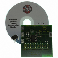
MCP6SX2DM-PCTLPD Microchip Technology, MCP6SX2DM-PCTLPD Datasheet - Page 25

MCP6SX2DM-PCTLPD
Manufacturer Part Number
MCP6SX2DM-PCTLPD
Description
BOARD DAUGHTER PICTAIL MCP6SX2
Manufacturer
Microchip Technology
Series
PICtail™r
Datasheets
1.AC164120.pdf
(36 pages)
2.MCP6SX2DM-PCTLPD.pdf
(28 pages)
3.MCP6SX2DM-PCTLPD.pdf
(12 pages)
Specifications of MCP6SX2DM-PCTLPD
Sensor Type
Light, Current Output
Interface
Analog
Sensitivity
850nm
Voltage - Supply
2.5 V ~ 5.5 V
Embedded
No
Utilized Ic / Part
MCP6001, MCP6S22, MCP6S92
Processor To Be Evaluated
MCP6Sx2
Lead Free Status / RoHS Status
Lead free / RoHS Compliant
Sensing Range
-
Lead Free Status / Rohs Status
Lead free / RoHS Compliant
Other names
MCP6SX2DM-PCTLPDR
MCP6SX2DM-PCTLPDR
MCP6SX2DM-PCTLPDR
Available stocks
Company
Part Number
Manufacturer
Quantity
Price
Company:
Part Number:
MCP6SX2DM-PCTLPD
Manufacturer:
MICROCHIP
Quantity:
12 000
3.1
3.2
3.3
2004 Microchip Technology Inc.
INTRODUCTION
HIGHLIGHTS
LESSON 1 – THERMISTOR
The Signal Analysis PICtail Daughter Board can capture a variety of DC and AC signals
from the RC0/AN4 I/O port pin of the PIC16F684 using the internal 10-bit ADC. Ensure
that the applied signal does not exceed 5V peak-to-peak. If the signal is DC, ensure
that the voltage levels do not fall below 0V or exceed +5V. If the signal is AC, DC
decouple the signal using a decoupling capacitor and ensure that the signal level does
not exceed the DC limits stated above. Lesson 1 demonstrates how a DC signal can
be displayed from a thermistor. Lesson 2 demonstrates how an AC signal can be
displayed from a photodiode.
In addition to capturing analog signals, the Signal Analysis PICtail Daughter Board can
generate low frequency sine waves from Pulse Width Modulated (PWM) signal from
the ECCP module. I/O port pin RC5 is connected to a low-pass RC filter (R1 and C4)
and made available as a test point on the edge of the PCB. Lesson 3 demonstrates
how a 125 Hz sine wave can be generated.
The following lessons are discussed in this chapter:
• Lesson 1 – Thermistor
• Lesson 2 – Photodiode
• Lesson 3 – Pulse Width Modulated Generated Sine Wave
A thermistor is a resistor that changes resistance in response to temperature changes.
Some have a positive temperature coefficient where the resistance increases with
temperature and others have a negative coefficient. For temperature measurement
purposes, the Negative Temperature Coefficient (NTC) versions are more linear.
The simplest configuration is shown in Figure 3-1. It is a resistor divider network where
the thermistor and a second resistor are connected in series between ground and a
voltage reference. The voltage between the resistors varies with the temperature and
can be measured via an A2D Converter. Also, this configuration has the added benefit
that voltage increases with temperature.
The voltage at the center is given by ADC counts = 1024 * R/(R+Rt). In this example,
the thermistor specified for 10 kΩ at 25C. The bottom resistor is chosen to be 3.3 kΩ.
That means 254 ADC counts correlates to 25C. Since the ADC is referenced to 5V
(nominal) 254 counts * 5/1024 = 1.241V.
Start the PICkit 1 Signal Analysis PC Application. Select the Real Time button, click on
the Strip Chart icon, and then click Go. By changing the temperature of the thermistor,
the response can be observed in real-time on the strip chart display. An example
screen capture is shown in Figure 3-2.
For more information about thermistors, see Microchip Application Notes AN685,
AN689, AN867 and AN897, available on the PICkit 1 CD-ROM and on the Microchip
web site: www.microchip.com.
Chapter 3. Lesson Projects
DAUGHTER BOARD USER’S GUIDE
SIGNAL ANALYSIS PICtail™
DS51476A-page 21


