TMPSNS-RTD1 Microchip Technology, TMPSNS-RTD1 Datasheet - Page 19
TMPSNS-RTD1
Manufacturer Part Number
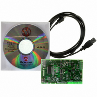
TMPSNS-RTD1
Description
BOARD EVAL PT100 RTD TEMP SENSOR
Manufacturer
Microchip Technology
Datasheets
1.MCP3301-CIMS.pdf
(32 pages)
2.PCM18XR1.pdf
(438 pages)
3.MCP6S22DM-PICTL.pdf
(43 pages)
4.TMPSNS-RTD1.pdf
(26 pages)
Specifications of TMPSNS-RTD1
Sensor Type
Temperature
Interface
USB
Embedded
Yes, MCU, 8-Bit
Utilized Ic / Part
MCP3301, MCP6S26, PIC18F2550
Processor To Be Evaluated
MCP6S26, MCP3301, MCP6024, MCP41010, PIC18F2550, TC1071, MCP6002
Data Bus Width
12 bit
Interface Type
USB
Lead Free Status / RoHS Status
Not applicable / Not applicable
Voltage - Supply
-
Sensitivity
-
Sensing Range
-
Lead Free Status / RoHS Status
Lead free / RoHS Compliant, Not applicable / Not applicable


5.2
The analog functions are programmed through the SPI
interface using 16-bit words (see Figure 5-1 and
Figure 5-2). This data is sent to two of three 8-bit regis-
ters: Instruction Register (Register 5-1), Gain Register
(Register 5-2) and Channel Register (Register 5-3).
The power-up defaults for these three registers are:
• Instruction Register: 000x xxx0
• Gain Register: xxxx x000
• Channel Register: xxxx x000
REGISTER 5-1:
2003 Microchip Technology Inc.
Registers
bit 7-5
bit 4-1
bit 0
INSTRUCTION REGISTER
M2-M0: Command Bits
000 = NOP (Default) (Note 1)
001 = PGA enters Shutdown Mode as soon as a full 16-bit word is sent and CS is raised.
010 = Write to register.
011 = NOP (reserved for future use) (Note 1)
1XX = NOP (reserved for future use) (Note 1)
Unimplemented: Read as ‘0’ (reserved for future use)
A0: Indirect Address Bit
1 = Addresses the Channel Register
0 = Addresses the Gain Register (Default)
Legend:
R = Readable bit
-n = Value at POR
Note 1: All other bits in the 16-bit word (including A0) are “don’t cares”.
bit 7
W-0
M2
(Notes 1 and 2)
2: The device exits Shutdown mode when a valid command (other than NOP or Shut-
down) is sent and CS is raised; that valid command will be executed. Shutdown
does not toggle.
W-0
M1
W-0
M0
W = Writable bit
’1’ = Bit is set
U-x
—
Thus, these devices are initially programmed with the
Instruction Register set for NOP (no operation), a gain
of +1 V/V and CH0 as the input channel.
5.2.1
The Instruction Register has 3 command bits and 1
indirect address bit; see Register 5-1. The command
bits include a NOP (000) to support daisy chaining (see
Section 5.3, “Registers”); the other NOP commands
shown should not be used (they are reserved for future
use). The device is brought out of Shutdown mode
when a valid command, other than NOP or Shutdown, is
sent and CS is raised.
U = Unimplemented bit, read as ‘0’
’0’ = Bit is cleared
U-x
—
INSTRUCTION REGISTER
MCP6S21/2/6/8
U-x
—
x = Bit is unknown
U-x
—
DS21117A-page 19
bit 0
W-0
A0
Related parts for TMPSNS-RTD1
Image
Part Number
Description
Manufacturer
Datasheet
Request
R

Part Number:
Description:
Manufacturer:
Microchip Technology Inc.
Datasheet:
Part Number:
Description:
Manufacturer:
Microchip Technology Inc.
Datasheet:
Part Number:
Description:
Manufacturer:
Microchip Technology Inc.
Datasheet:
Part Number:
Description:
Manufacturer:
Microchip Technology Inc.
Datasheet:
Part Number:
Description:
Manufacturer:
Microchip Technology Inc.
Datasheet:
Part Number:
Description:
Manufacturer:
Microchip Technology Inc.
Datasheet:
Part Number:
Description:
Manufacturer:
Microchip Technology Inc.
Datasheet:
Part Number:
Description:
Manufacturer:
Microchip Technology Inc.
Datasheet: