ATQT600 Atmel, ATQT600 Datasheet - Page 39
ATQT600
Manufacturer Part Number
ATQT600
Description
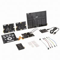
KIT EVAL TOUCH FOR QT600
Manufacturer
Atmel
Series
QTouch™r
Specifications of ATQT600
Sensor Type
Touch Screen
Interface
USB
Embedded
Yes, Other
Utilized Ic / Part
ATtiny88, ATmega324PA, ATxmega128A1
Processor To Be Evaluated
ATtiny88, ATmega324, ATxmega128
Data Bus Width
8 bit, 16 bit
Interface Type
USB
Maximum Operating Temperature
+ 85 C
Minimum Operating Temperature
- 40 C
Operating Supply Voltage
1.6 V to 3.6 V
Silicon Manufacturer
Atmel
Kit Application Type
Sensor
Application Sub Type
Touch Sensor
Kit Contents
USB Bridge, MCU Cards, Touchpad Cards
Svhc
No SVHC (15-Dec-2010)
Mcu Supported Families
ATtiny88,
Rohs Compliant
Yes
Lead Free Status / RoHS Status
Lead free / RoHS Compliant
Voltage - Supply
-
Sensitivity
-
Sensing Range
-
Lead Free Status / Rohs Status
Lead free / RoHS Compliant
Available stocks
Company
Part Number
Manufacturer
Quantity
Price
Company:

Part Number:
ATQT600
Manufacturer:
Atmel
Quantity:
135


4.2.4
4.2.4.1
4.2.4.2
Touch Sensors Design Guide
Interconnection
X Routing
Y Routing
X routing is fairly trivial as long as RC time constant rules are observed. Nearby foreign signals that have
large kHz frequency
the charge transfer. Examples of circuits to consider include D-class amplifier signals, LCD or LED drive
signals.
X routing is not touch sensitive, and so X traces can be routed with ease on any layer of a PCB, including
the side nearest to touch. However, X routing must also take the Y routing into account.
Y routing must be more carefully considered, due to Cp build-up and the need to avoid an effect called
false key detection. Y routing is only very weakly touch sensitive, so it is good practice to run Y traces on
a layer that is far from touch.
The first factor, Cp build-up, is easily dealt with by avoiding routing Y traces over or close to ground
planes (or other power planes).
The second factor, false key detection, can occur wherever there is an interaction of the Y traces with the
X traces. Remember that anywhere where X and Y get close (less than 10 mm), and the field between
them is allowed to be influenced by touch, you have a potential key or at least a touch sensitive zone that
you do not expect (see
Figure 4-8.
1. High kHz to hundreds of kHz in particular.
Potential False Key
(1)
Potential False
Key Detection
switching transients should be routed well away from X traces as they can disturb
Figure
X Trace
4-8).
Y Trace
Mutual-capacitance Zero-dimensional Sensors
Overlying Panel
10620D–AT42–04/09
4-7
Related parts for ATQT600
Image
Part Number
Description
Manufacturer
Datasheet
Request
R

Part Number:
Description:
DEV KIT FOR AVR/AVR32
Manufacturer:
Atmel
Datasheet:

Part Number:
Description:
INTERVAL AND WIPE/WASH WIPER CONTROL IC WITH DELAY
Manufacturer:
ATMEL Corporation
Datasheet:
Part Number:
Description:
Low-Voltage Voice-Switched IC for Hands-Free Operation
Manufacturer:
ATMEL Corporation
Datasheet:
Part Number:
Description:
MONOLITHIC INTEGRATED FEATUREPHONE CIRCUIT
Manufacturer:
ATMEL Corporation
Datasheet:
Part Number:
Description:
AM-FM Receiver IC U4255BM-M
Manufacturer:
ATMEL Corporation
Datasheet:
Part Number:
Description:
Monolithic Integrated Feature Phone Circuit
Manufacturer:
ATMEL Corporation
Datasheet:
Part Number:
Description:
Multistandard Video-IF and Quasi Parallel Sound Processing
Manufacturer:
ATMEL Corporation
Datasheet:
Part Number:
Description:
High-performance EE PLD
Manufacturer:
ATMEL Corporation
Datasheet:
Part Number:
Description:
8-bit Flash Microcontroller
Manufacturer:
ATMEL Corporation
Datasheet:
Part Number:
Description:
2-Wire Serial EEPROM
Manufacturer:
ATMEL Corporation
Datasheet: