MT9M131C12STCD ES Aptina LLC, MT9M131C12STCD ES Datasheet - Page 5
MT9M131C12STCD ES
Manufacturer Part Number
MT9M131C12STCD ES
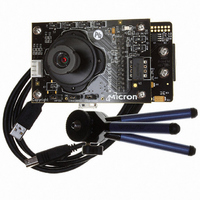
Description
KIT DEV FOR MT9M131
Manufacturer
Aptina LLC
Series
Micron®DigitalClarity®r
Datasheets
1.MT9P031I12STCH_ES.pdf
(6 pages)
2.MT9M131C12STCH_ES.pdf
(2 pages)
3.MT9M131C12STCH_ES.pdf
(14 pages)
Specifications of MT9M131C12STCD ES
Sensor Type
CMOS Imaging, Color (RGB)
Sensing Range
1.3 Megapixel
Interface
USB
Sensitivity
15 fps
Voltage - Supply
1.8 V ~ 3.1 V
Embedded
No
Utilized Ic / Part
MT9M131
Silicon Manufacturer
Aptina Imaging
Application Sub Type
Image Sensor
Kit Application Type
Sensing - Image / Light
Silicon Core Number
MT9M131
Lead Free Status / RoHS Status
Lead free / RoHS Compliant
Other names
557-1246


Internal Architecture
Typical Connection
Figure 3:
PDF:09005aef824c90f2/Source: 09005aef824c90f9
MT9M131_LDS_2.fm - Rev. A 3/07 EN
Power-on Reset
Serial Interface
Master Clock
Two-Wire
1.8V–3.1V
I/O Digital
Typical Configuration (Connection)
Digital GND
SADDR
SCLK
S
CLKIN
RESET#
OE#
STANDBY
DATA
Notes:
Core Digital
2.8V
1. For two-wire serial interface, a 1.5KΩ resistor is recommended, but may be greater for
2. V
3. Logic levels of all input pins, that is, S
Internally, the MT9M131 consists of a sensor core and an IFP. The IFP is divided in two
sections: the colorpipe (CP), and the camera controller (CC). The sensor core captures
raw Bayer-encoded images that are then input in the IFP. The CP section of the IFP
processes the incoming stream to create interpolated, color-corrected output, and the
CC section controls the sensor core to maintain the desired exposure and color balance,
and to support snapshot modes.
The MT9M131 supports a range of color formats derived from four primary color repre-
sentations: YCbCr, RGB, raw Bayer (unprocessed, directly from the sensor), and
processed Bayer (Bayer format data regenerated from processed RGB). The device also
supports a variety of output signaling/timing options:
• Standard FV/LV video interface with gated pixel clocks
• Standard video interface with uniform clocking
• Progressive ITU-R BT.656 marker-embedded video interface with either gated or
Figure 3 shows typical MT9M131 device connections.
uniform pixel clocking
slower two-wire speed.
taken to avoid excessive noise injection in the V
must be equal to V
DD
FRAME_VALID
, V
2.8V Analog
LINE_VALID
AA
D
OUT
STROBE
PIXCLK
, VAAPIX must all be at the same potential, though if connected, care must be
[7:0]
Analog GND
To CMOS
Camera Port
To Xenon or LED
Flash Driver
DD
Q.
MT9M131: SOC Megapixel Digital Image Sensor
5
S
SCLK
ADDR
DATA
Micron Technology, Inc., reserves the right to change products or specifications without notice.
, CLKIN, SCLK, S
1.5KΩ
1.5KΩ
AA
/VAAPIX power domains.
0.1µF
D
V
DATA
GND
DD
Q
Q
, OE#, STANDBY, and RESET#
©2007 Micron Technology, Inc. All rights reserved.
1µF
Typical Connection
0.1µF
0.1µF
V
AA
D
A
/VAAPIX
V
GND
GND
DD
Preliminary
1µF
1µF
Related parts for MT9M131C12STCD ES
Image
Part Number
Description
Manufacturer
Datasheet
Request
R

Part Number:
Description:
SENSOR IMAGE VGA COLOR CMOS PLCC
Manufacturer:
Aptina LLC
Datasheet:

Part Number:
Description:
IC SENSOR IMAGE COLOR 48CLCC
Manufacturer:
Aptina LLC
Datasheet:

Part Number:
Description:
SENSOR IMAGE 1.3MP CMOS 48-CLCC
Manufacturer:
Aptina LLC
Datasheet:

Part Number:
Description:
SENSOR IMAGE 2MP CMOS 48-CLCC
Manufacturer:
Aptina LLC
Datasheet:

Part Number:
Description:
SENSOR IMAGE VGA MONO 52IBGA
Manufacturer:
Aptina LLC
Datasheet:

Part Number:
Description:
SENSOR IMAGE VGA COLOR 48CLCC
Manufacturer:
Aptina LLC
Datasheet:

Part Number:
Description:
SENSOR IMAGE COLOR CMOS 48-PLCC
Manufacturer:
Aptina LLC
Datasheet:

Part Number:
Description:
KIT HEAD BOARD FOR MT9P031
Manufacturer:
Aptina LLC
Datasheet:

Part Number:
Description:
KIT HEAD BOARD FOR MT9D131
Manufacturer:
Aptina LLC
Datasheet:

Part Number:
Description:
KIT HEAD BOARD FOR MT9P031
Manufacturer:
Aptina LLC
Datasheet:
Part Number:
Description:
SENSOR IMAGE VGA COLOR CMOS PLCC
Manufacturer:
Aptina LLC
Datasheet:
Part Number:
Description:
IC SENSOR IMAGE COLOR 48CLCC
Manufacturer:
Aptina LLC
Datasheet:
Part Number:
Description:
SENSOR IMAGE 2MP CMOS 48-CLCC
Manufacturer:
Aptina LLC
Datasheet:
