AS5040 AB austriamicrosystems, AS5040 AB Datasheet
AS5040 AB
Specifications of AS5040 AB


Related parts for AS5040 AB


AS5040 AB Summary of contents
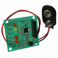
Page 1
... LEDs for magnet status outputs MagInc, MagDec On-board 5V linear voltage regulator for 7,5…12V supplies 9V battery connector for standalone operation Dimensions: 35mm x 37mm (1.38 x 1.46 inch) Revision A.03 04. Jul.06 Figure 1: AS5040 Adapter PCB: top and bottom view www.austriamicrosystems.com ADAPTER PCB OPERATION MANUAL Page ...
Page 2
... VDD3V3 PWM_LSB 16 VDD5V CSn CLK Table 1: Pin description DO www.austriamicrosystems.com Type Description Magnet Field Magnitude INCrease; active low, indicates a DO_OD distance reduction between the magnet and the device surface. Magnet Field Magnitude DECrease; active low, indicates DO_OD a distance increase between the device and the magnet. ...
Page 3
... The digital angle information is available in several formats: as serial 10-bit data stream, as pulse-width modulated (PWM) signal or as quadrature incremental signal www.austriamicrosystems.com Page ...
Page 4
... I/O IC2 or IC3 level not required *) 3.0….3.6V not required *) 4.5….5.5V 3.3V type, e.g. LE33C 3.3V (ST Micro) 5.0V type 5.0V e.g. 75L05 www.austriamicrosystems.com remark short VDD5V and VDD3V3 short VDD5V and VDD3V3 PCB delivery status Page ...
Page 5
... For programming the AS5040, 3 digital signals are required: CSn, Prog and CLK (see datasheet). For permanent writing, VPROG must be elevated to 7.5V during the programming cycle. For immediate programming, this PCB can be connected directly to the AS5040 demoboard (available separately), where all the programming timings are generated by the onboard microcontroller. Revision A.03 04. Jul.06 www.austriamicrosystems.com Page ...
Page 6
... Figure 7: AS5040 / AS5035 Adapter board dimensions. Revision A.03 04. Jul.06 AS5040 adapter board: top view Layout: Bottom Components 1.26 (32.1) 0.59 (14.95) 0.08 (2.1) All Dimensions in inch (mm) 0 www.austriamicrosystems.com 1.38 (34.95) Page ...
Page 7
... AS5040 demoboard software This configuration uses the same hardware connection as 8.1.2, but additionally the AS5040 demoboard software is running. All indicators on the demoboard will be displayed on the PC screen as well. Figure 8: AS5040 demoboard and Adapter PCB Revision A.03 04. Jul.06 www.austriamicrosystems.com Page ...
Page 8
... DC motor commutation ) Programming the resolution at 7,8 bits Programming the Index bit width bits Putting the AS5040 in Alignment mode Permanently programming (OTP) the incremental mode, resolution and Index bit width. Reversing the direction of rotation www.austriamicrosystems.com angle as 10bit-word incremental output mode Page ...
Page 9
... AS5040 Demoboard For programming, keep these 6 wires as short as possible! 7 PROG 6 CSN CLK 3 5VUSB 2 VDD3V3 1 VSS 22k *see Text www.austriamicrosystems.com connect to USB interface on PC VPROG µC 1 10µF VSS GND 7.5 … 8.0V only required for OTP programming GND Page ...
Page 10
... It is possible to write "1"s into the OTP register at subsequent programming cycles. However, a programmed "1" cannot be cleared any more after programming. Note that the chip will not be programmed, as long as no programming voltage is applied to Vzapp, although the software will issue a warning message that the chip will be permanently programmed. Revision A.03 04. Jul.06 ). www.austriamicrosystems.com Page ...
Page 11
... Higher operating voltages can be handled with an external voltage regulator (e.g. > 7,5V with an external 78L05). The maximum output voltage level on the A,B and Index pins corresponds to the voltage at pin VDD5V. Figure 11: Incremental Outputs and power supply options Revision A.03 04. Jul.06 www.austriamicrosystems.com Page ...
Page 12
... Revision A.03 04. Jul.06 Output A Md0 Div1 Div0 256ppr 128ppr 64ppr 32ppr 512ppr 256ppr 128ppr 64ppr Table 3: Incremental signal generation www.austriamicrosystems.com Output B 256 ppr 128ppr 64ppr 32ppr direction cw/ccw direction cw/ccw direction cw/ccw direction cw/ccw … Page ...
Page 13
... Fax: +39 02 4585 773 austriamicrosystems France S.A.R.L. 124, Avenue de Paris F-94300 Vincennes, France Phone: + Fax: + austriamicrosystems Switzerland AG Rietstrasse 4 CH 8640 Rapperswil, Switzerland Phone: +41 55 220 9008 Fax: +41 55 220 9001 austriamicrosystems UK, Ltd. 88, Barkham Ride, Finchampstead, Wokingham Berkshire RG40 4ET, United Kingdom ...
Page 14
... Therefore, prior to designing this product into a system necessary to check with austriamicrosystems for current information. This product is intended for use in normal commercial applications. ...