DM164120-1 Microchip Technology, DM164120-1 Datasheet - Page 31
DM164120-1
Manufacturer Part Number
DM164120-1
Description
BOARD DEMO PICKIT 2 LP COUNT
Manufacturer
Microchip Technology
Type
MCUr
Datasheet
1.DM164120-1.pdf
(42 pages)
Specifications of DM164120-1
Contents
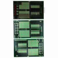
3 Boards (1 Populated, 2 Bare)
Processor To Be Evaluated
PIC16F690
Silicon Manufacturer
Microchip
Core Architecture
PIC
Core Sub-architecture
PIC16
Silicon Core Number
PIC16F
Silicon Family Name
PIC16F6xxx
Rohs Compliant
Yes
Lead Free Status / RoHS Status
Lead free / RoHS Compliant
For Use With/related Products
28-pin PIC16C, 16F, 18C, 18F
Lead Free Status / Rohs Status
Lead free / RoHS Compliant
Available stocks
Company
Part Number
Manufacturer
Quantity
Price
Company:

Part Number:
DM164120-1
Manufacturer:
Microchip Technology
Quantity:
135


© 2005 Microchip Technology Inc.
3.2.9
Timer0 is a counter implemented in the processor. It may be used to count processor
clock cycles or external events. Lesson 9 configures it to count instruction cycles and
set a flag when it rolls over. This frees up the processor to do meaningful work rather
than just wasting cycles.
Timer0 is an 8-bit counter with an optional prescaler, which is configured to divide by
256 before reaching the Timer0 counter.
FIGURE 3-7:
TMR0 is a Special Function Register (SFR) and may be read or modified by the
program. The Prescaler is not a SFR and thus cannot be read or modified by the
program. However, writing to TMR0 clears the Prescaler.
The timer may be fed either by the same clock that drives the processor or by an
external event. Driven by the processor clock, it increments once for every instruction
cycle. This is a convenient method of marking time, better than delay loops, as it allows
the processor to work on the problem rather than waste cycles in delay loops.
The prescaler is configured through the OPTION_REG, see Figure 3-8.
FIGURE 3-8:
Lesson 9 configures Timer0 with the Prescaler for a maximum delay on Timer0. The
prescaler will divide the processor clock by 256 and Timer0 will divide that by 256
again. Thus, Timer0 Flag will be set every 65536 μs (0.0000001 second * 256 * 256),
or about 15 times a second. The main program sits in a loop waiting for the rollover and
when it does, it increments the display and then loops back.
Legend:
Clock/4 or
T0CKI pin
bit 7
Note:
X:
T0CS: Timer0 Clock Source 0 for Instruction Clock.
T0SE: Timer0 Source Edge – Don’t care when connected to instruction clock.
PSA:
PS:
X
Lesson 9: Timer0
See PIC16F690 Timer0 section for more details.
Prescaler may be configured
to divide by 2, 4, 8, 16, 32, 64,
128 or 256.
Don’t cares – not Timer0 related.
Prescaler Assignment 0 assigns to Timer0.
Prescaler rate select ‘111’ – full prescaler, divide by 256.
X
TIMER0 SIMPLIFIED
PRESCALER CONFIGURATION THROUGH OPTION_REG
T0CS
Prescaler
LPC Demo Board Lessons
T0SE
PSA
TMR0
PS2
Flag set when
TMR0 overflows.
Must be cleared
in software.
PS1
DS51556A-page 27
T0IF
PS0
bit 0
Related parts for DM164120-1
Image
Part Number
Description
Manufacturer
Datasheet
Request
R

Part Number:
Description:
SERIES CONNECTION; 16 DIODES
Manufacturer:
Altech Corp.
Datasheet:

Part Number:
Description:
Manufacturer:
Microchip Technology Inc.
Datasheet:
Part Number:
Description:
Manufacturer:
Microchip Technology Inc.
Datasheet:
Part Number:
Description:
Manufacturer:
Microchip Technology Inc.
Datasheet:
Part Number:
Description:
Manufacturer:
Microchip Technology Inc.
Datasheet:
Part Number:
Description:
Manufacturer:
Microchip Technology Inc.
Datasheet:
Part Number:
Description:
Manufacturer:
Microchip Technology Inc.
Datasheet:
Part Number:
Description:
Manufacturer:
Microchip Technology Inc.
Datasheet:
Part Number:
Description:
Manufacturer:
Microchip Technology Inc.
Datasheet: