DM163022 Microchip Technology, DM163022 Datasheet
DM163022
Manufacturer Part Number
DM163022
Description
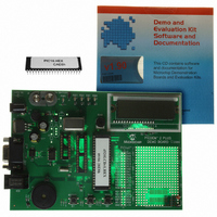
BOARD DEMO PICDEM-2 PLUS
Manufacturer
Microchip Technology
Type
MCUr
Specifications of DM163022
Contents
Board, CD, Sample Part
Processor To Be Evaluated
PIC 16 and PIC 18
Interface Type
RS-232
Silicon Manufacturer
Microchip
Core Architecture
PIC
Core Sub-architecture
PIC16, PIC18
Silicon Core Number
PIC16F, PIC18F
Silicon Family Name
PIC16F8xx, PIC18F4xxx
Rohs Compliant
NA
Lead Free Status / RoHS Status
Lead free / RoHS Compliant
For Use With/related Products
PICDEM 2 Plus
Lead Free Status / Rohs Status
Lead free / RoHS Compliant
Other names
DM163022R
DM163022R
DM163022R
Available stocks
Company
Part Number
Manufacturer
Quantity
Price
Company:

Part Number:
DM163022
Manufacturer:
Microchip Technology
Quantity:
135
Company:
Part Number:
DM163022-1
Manufacturer:
MICROCHIP
Quantity:
12 000


In-Circuit Debugging Basics
Traditionally, embedded systems engineers use in-circuit
emulators (ICE) to develop and debug their designs and
then programmers to transfer the code to the devices. The
in-circuit debugging logic, when implemented, is part of the
actual microcontroller silicon and provides a low-cost
alternative to a more expensive ICE. In-circuit debugging
offers these benefits:
·
·
·
·
However, it has the following trade-offs:
·
·
·
MPLAB®ICD 2 In-Circuit Debugger/Programmer
All-in-one Debugger/Programmer
Solution for Flash Products
The MPLAB ICD 2 (In-Circuit Debugger 2) allows
debugging and programming of PIC®and dsPIC®Flash
microcontrollers using the powerful graphical user interface
of the MPLAB Integrated Development Environment (IDE),
included with each kit. The MPLAB ICD 2 is connected to
the design engineer's PC using USB or RS-232 interface
and can be connected to the target via an ICD connector.
The connector uses two device I/O pins that are shared
between in-circuit debugging and In-Circuit Serial
Programming™.
Host System Requirements
·
·
·
·
·
·
Low cost
Minimum of extra hardware
Expensive sockets or adapters are not needed
Debugging and programming a production line board is
possible
Use of some target system resources such as I/O
pins, program memory, data memory, and stack
space. As a result, some portions of an embedded
application may not be debugged.
Triggering and breakpointing are limited to the built-in
capabilities of the in-circuit debugging logic.
The target chip must be running with a clock and a
supply voltage. Often an emulator probe can run
without external hardware.
PC-compatible system with a Intel Pentium®class or
higher processor, or equivalent
A minimum of 32 MB RAM
A minimum of 40 MB available hard drive space
CD-ROM drive (for use with the accompanying CD)
Available USB or RS-232 port
Microsoft®Windows®98, Windows NT®4.0,
Windows 2000 or Windows XP . USB support may be
limited by the Windows operating system, particularly
Windows 98/NT.
Features
·
·
·
·
·
·
·
·
·
·
·
Products Supported
The MPLAB ICD 2 currently supports most PIC and dsPIC
Flash microcontrollers. Flash PICmicro MCU’s not
supported are PIC16F72/73/74/76/77/83/84A.
The MPLAB ICD 2 firmware is continually being updated to
add support for new devices. A review of the README file
located in MPLAB IDE is recommended for the most current
list of supported parts. As new device firmware becomes
available, free downloads are available at
www.microchip.com.
USB (Full Speed 2 Mbits/s) and RS-232 interface to
host PC
Real-time execution
MPLAB IDE compatible (free copy included)
Built-in over voltage/short circuit monitor
Firmware upgradeable from PC/web download
Totally enclosed
Supports low voltage to 2.0 volts (2.0 to 6.0 range)
Diagnostic LED's (Power, Busy, Error)
Read/Write program and data memory of
microcontroller
Erase of program memory space with verification
Freeze-peripherals at breakpoint
Related parts for DM163022
Image
Part Number
Description
Manufacturer
Datasheet
Request
R

Part Number:
Description:
Manufacturer:
Microchip Technology Inc.
Datasheet:
Part Number:
Description:
Manufacturer:
Microchip Technology Inc.
Datasheet:
Part Number:
Description:
Manufacturer:
Microchip Technology Inc.
Datasheet:
Part Number:
Description:
Manufacturer:
Microchip Technology Inc.
Datasheet:
Part Number:
Description:
Manufacturer:
Microchip Technology Inc.
Datasheet:
Part Number:
Description:
Manufacturer:
Microchip Technology Inc.
Datasheet:
Part Number:
Description:
Manufacturer:
Microchip Technology Inc.
Datasheet:
Part Number:
Description:
Manufacturer:
Microchip Technology Inc.
Datasheet:
DM163022 Summary of contents
Page 1
MPLAB®ICD 2 In-Circuit Debugger/Programmer In-Circuit Debugging Basics Traditionally, embedded systems engineers use in-circuit emulators (ICE) to develop and debug their designs and then programmers to transfer the code to the devices. The in-circuit debugging logic, when implemented, is part of ...
Page 2
... PICDEM™ 2 Plus Demonstration Board - DV163022) DV164007 ICD 2 Module ws AC162049 Universal Programming Module AC162048 RS-232 and Power Supply Kit DM163022 PICDEM 2 Plus Demonstration Board LED’s, RS-232 Port, Piezo Sounder, Temperature Sensor, Demonstration Programs, Unassembled Source Code and More) AC162050 Header Interface (8P DIP) for PIC12F629/675 AC162051 ...