DM163022 Microchip Technology, DM163022 Datasheet
DM163022
Specifications of DM163022
DM163022R
Available stocks


Related parts for DM163022

DM163022 Summary of contents
Page 1
... Microchip Technology Inc. PICDEM™ 2 Plus Demonstration Board User’s Guide DS51275D ...
Page 2
... PowerInfo, PowerMate, PowerTool, REAL ICE, rfLAB, Select Mode, Smart Serial, SmartTel, Total Endurance, UNI/O, WiperLock and ZENA are trademarks of Microchip Technology Incorporated in the U.S.A. and other countries. SQTP is a service mark of Microchip Technology Incorporated in the U.S.A. All other trademarks mentioned herein are property of their respective companies. ...
Page 3
... Analog Input ........................................................................................... 18 A.8 ICD Connector ........................................................................................ 18 A.9 Temperature Sensor ............................................................................... 18 A.10 Serial EEPROM ...................................................................................... 18 A.11 LCD ........................................................................................................ 18 A.12 Sample Devices ...................................................................................... 19 A.13 Board Layout and Schematics ................................................................ 20 Index.............................................................................................................................. 23 Worldwide Sales and Service .................................................................................... 24 © 2007 Microchip Technology Inc. PICDEM™ 2 PLUS Table of Contents USER’S GUIDE DS51275D-page iii ...
Page 4
... NOTES: DS51275D-page iv © 2007 Microchip Technology Inc. ...
Page 5
... ICE or ICD. • Chapter 3. “Tutorial” – Provides a detailed description of the tutorial program. • Appendix A. “Hardware Detail” – Describes in detail the hardware of the PICDEM 2 Plus demonstration board. © 2007 Microchip Technology Inc. Preface NOTICE TO CUSTOMERS PICDEM™ 2 PLUS USER’S GUIDE ® ...
Page 6
... Optional arguments mcc18 [options] file [options] Choice of mutually exclusive errorlevel {0|1} arguments selection Replaces repeated text var_name [, var_name...] Represents code supplied by void main (void) user { ... } © 2007 Microchip Technology Inc. Examples ® IDE User’s Guide ...
Page 7
... MPLAB ICE Emulator User’s Guide (DS51159) ® • MPLAB ICD 2 In-Circuit Debugger Quick Start Guide (DS51268) © 2007 Microchip Technology Inc. ® IDE installation directory ® Mid-Range MCU Family Reference Manual (DS33023) ® 18C MCU Family Reference Manual (DS39500) ® ...
Page 8
... Programmers – The latest information on Microchip programmers. These include the MPLAB PM3 and PRO MATE Plus and PICkit™ 1 development programmers. DS51275D-page 4 ® II device programmers and the PICSTART © 2007 Microchip Technology Inc. ® ® ...
Page 9
... Technical support is available through the web site at: http://support.microchip.com. DOCUMENT REVISION HISTORY Revision D (August 2007) • Updated document to new format, including the addition of a preface. • Corrected schematic in Figure A-2 and updated Figure A-3. Revision C (November 2006) Revision B (February 2004) © 2007 Microchip Technology Inc. DS51275D-page 5 ...
Page 10
... NOTES: DS51275D-page 6 © 2007 Microchip Technology Inc. ...
Page 11
... Application Notes If you are missing any part of the kit, please contact your nearest Microchip sales office listed in the back of this publication for help. © 2007 Microchip Technology Inc. PICDEM™ 2 PLUS USER’S GUIDE ® ICE) or with an in-circuit debugger (such as MPLAB ...
Page 12
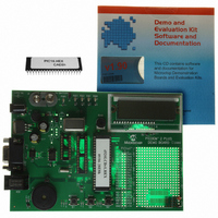
... Timer1 clock operation • Jumper J7 to disconnect on-board RC oscillator (approximately 2 MHz) • 32K x 8 Serial EEPROM • LCD display • Piezo buzzer • Prototype area for user hardware • Microchip TC74 thermal sensor DS51275D-page 8 © 2007 Microchip Technology Inc. ...
Page 13
... These programs may be used with the included sample devices, with an In-Circuit Emulator (ICE) or with an In-Circuit Debugger (ICD). For each type of device (PIC16 or PIC18), demo source code (several ASM files) and compiled code (one Hex file) are provided. © 2007 Microchip Technology Inc ...
Page 14
... NOTES: DS51275D-page 10 © 2007 Microchip Technology Inc. ...
Page 15
... MPLAB C18 (PIC18 devices only) Source code must be assembled or compiled into a hex file before it can be pro- grammed into the device. Microchip Technology’s MPASM assembler or MPLAB C18 C compiler may be used. Both are compatible with MPLAB IDE. Other assemblers/compilers may be used. For a list of these PIC MCU compatible language tools, see the Microchip web site (www ...
Page 16
... Modification on PICDEM 2 Plus J7 installed, Y2 empty, Y1 empty J7 removed, Y2 empty, crystal in Y1, caps in C4 and C5 J7 removed, oscillator in Y2 (Y1, C4, C5 empty) J7 removed, Y2 empty, resonator in Y1, caps in C4 and C5 J7 removed, Y2 empty, resonator in Y1, C4 and C5 empty ® ICD 2 USING USB © 2007 Microchip Technology Inc. ...
Page 17
... RB0. This mode contains code that will write to the external on-board EEPROM. Every two seconds, the code will write to a defined EEPROM address and store the current temperature in that address. © 2007 Microchip Technology Inc. PICDEM™ 2 PLUS USER’S GUIDE Chapter 3. Tutorial MCU and sensor is accomplished using the MSSP module ...
Page 18
... LCD is returned to an active clock display. The data that is sent to the LCD is also sent to the RS-232 serial port using the USART on the PIC MCU. A HyperTerminal™ program on the PC will be able to display the same information that is displayed on the LCD DS51275D-page 14 © 2007 Microchip Technology Inc. ...
Page 19
... FIGURE 3-1: © 2007 Microchip Technology Inc. TUTORIAL PROGRAM FLOWCHART Power-up PICDEM™ 2 Plus Voltmeter RA4 = Next RB0 = Now Buzzer RA4 = Next RB0 = Now Prd = 128 DC = 128 RA4 = -> RB0 = ++ Temperature RA4 = 3 Presses RA4 = Next RB0 = Now Temp = 022°C Clock RA4 = Next ...
Page 20
... Application notes with additional use examples are included on the CD-ROM. For information on how to reprogram the device with new or modified code, or how to restore the tutorial program, please see Section 2.1 “PICDEM™ 2 Plus as a Stand-Alone Board – Preprogrammed Device”. DS51275D-page 16 © 2007 Microchip Technology Inc. ...
Page 21
... RS-232 host through the DB9 connector. The port is configured as DCE and can be connected using a straight-through cable. The PIC16/PIC18 RX and TX pins are tied to the RX and TX lines of the MAX232A. © 2007 Microchip Technology Inc. PICDEM™ 2 PLUS USER’S GUIDE DS51275D-page 17 ...
Page 22
... There are three control lines (RA3:RA1) and four data lines (RD3:RD0 kΩ pot may be installed into R20 to adjust contrast on the LCD. If this is done, R5 and R6 need to be removed. DS51275D-page 18 to GND to provide an analog input to the parts with DD 2 C™ compatible serial © 2007 Microchip Technology Inc bus ...
Page 23
... TABLE A-1: PORT CONNECTIONS Device LEDs RS-232 S1 18-pin RB3:RB0 N/A MCLR RA4 RB0 28-pin RB3:RB0 RC6/RC7 MCLR RA4 RB0 40-pin RB3:RB0 RC6/RC7 MCLR RA4 RB0 © 2007 Microchip Technology Inc. Pot S2 S3 LCD EEPROM Buzzer R16 RA0 N/A N/A RA0 RA3:RA1 RC3/RC4 ...
Page 24
... J1 1 C17 C10 C11 PIN C14 U5 P1 ICD Q1 DS51275D-page 20 RB3 RB2 RB1 RB0 ( ) ( ) ( ) ( ) J6 Y2 R20 CONTRAST U2 U1 RA0 1 1 C19 0 1 R16 PIN 7 40 PIN RA4 RB0 RESET LCD1 +5V GND PICDEM™ 2 PLUS DEMO BOARD ©2002 © 2007 Microchip Technology Inc. ...
Page 25
... FIGURE A-2: PICDEM™ 2 PLUS SCHEMATIC © 2007 Microchip Technology Inc. DS51275D-page 21 ...
Page 26
... FIGURE A-3: PICDEM™ 2 PLUS SCHEMATIC (CONTINUED) DS51275D-page 22 © 2007 Microchip Technology Inc. ...
Page 27
... Red Display .............................................8 M Microchip Internet Web Site ....................................... 4 MPASM Assembler .................................................. 11 MPLAB C18 C Compiler .......................................... 11 MPLAB ICD 2...................................... 7 MPLAB ICE ...........................................................7 MPLAB ICE 2000 ..................................................... 17 MPLAB IDE .............................................................. 11 © 2007 Microchip Technology Inc. PICDEM™ 2 PLUS USER’S GUIDE Index O 18 Oscillator Options..................................................... 18 , Oscillator Selection .................................................. 12 P PIC16 ......................................................................... 7 Tutorial Program ...
Page 28
... Fax: 886-3-572-6459 Taiwan - Kaohsiung Tel: 886-7-536-4818 Fax: 886-7-536-4803 Taiwan - Taipei Tel: 886-2-2500-6610 Fax: 886-2-2508-0102 Thailand - Bangkok Tel: 66-2-694-1351 Fax: 66-2-694-1350 © 2007 Microchip Technology Inc. <Condition> EUROPE Austria - Wels Tel: 43-7242-2244-39 Fax: 43-7242-2244-393 Denmark - Copenhagen Tel: 45-4450-2828 Fax: 45-4485-2829 France - Paris ...