DM300018 Microchip Technology, DM300018 Datasheet - Page 94
DM300018
Manufacturer Part Number
DM300018
Description
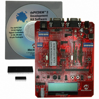
BOARD DEMO DSPICDEM 2
Manufacturer
Microchip Technology
Type
MCUr
Specifications of DM300018
Contents
*
Processor To Be Evaluated
dsPIC30F
Interface Type
RS-232
Silicon Manufacturer
Microchip
Core Architecture
DsPIC
Core Sub-architecture
DsPIC30
Silicon Core Number
DsPIC30F
Silicon Family Name
DsPIC30F2xxx, DsPIC30F3xxx
Lead Free Status / RoHS Status
Not applicable / RoHS Compliant
For Use With/related Products
dsPIC30F
Lead Free Status / Rohs Status
Lead free / RoHS Compliant
Other names
Q2448034
Available stocks
Company
Part Number
Manufacturer
Quantity
Price
Company:

Part Number:
DM300018
Manufacturer:
MICROCHIP
Quantity:
12 000


dsPICDEM 2 Development Board User’s Guide
DS51558A-page 88
TABLE 14-1:
14.1.1
The dsPICDEM™ 2 Development Board may be powered by a +9V AC/DC wall
adapter. A DC voltage regulator is provided so as to regulate the +9V input from the
wall adaptor and supply +5V to V
to supply power to the board from a wall adaptor, the jumpers JP1 and JP2 need to be
installed and power should be supplied via the J4 jack. The PWR ON LED, D1 will
illuminate if the power has been applied to the board appropriately.
The schematics of the power supply circuits are shown in Figure A-8: “dsPICDEM™
2 Development Board Schematic (Sheet 7 of 7)”.
No.
10
12
13
14
15
16
17
18
11
1
2
3
4
5
6
7
8
9
CAN Port
(see Section 14.1.6)
CAN Transceiver
(see Section 14.1.6)
CAN Header
(see Section 14.1.6)
External Power Supply Inputs
(see Section 14.1.1)
Power On LED
(see Section 14.1.1)
Power Supply jumpers
(see Section 14.1.1)
Voltage Regulator
(see Section 14.1.1)
UART 1 Header
(see Section 14.1.7)
DIP Switch, debug selector for general
purpose device sockets
(see Section 14.1.4)
Alternate UART 1 header
(see Section 14.1.7)
Device Headers, concentric sockets
for dsPIC30F devices
(see Section 14.1.2)
Crystal Oscillator, for General Purpose
Devices
(see Section 14.1.3)
Reset Pushbutton Switch
(see Section 14.1.13)
UART 2 header
(see Section 14.1.7)
Output LEDs
(see Section 14.1.9)
LED Header
(see Section 14.1.9)
Pushbutton Switches S5 and S6
(see Section 14.1.8)
Switch S5 header
(see Section 14.1.8)
Power Supply
Hardware Element
dsPICDEM™ 1.1 DEVELOPMENT BOARD HARDWARE
DD
and AV
DD
No.
19
20
21
22
23
24
25
26
27
28
29
30
31
32
33
34
35
pins on the dsPIC30F device. In order
Switch S6 header
(see Section 14.1.8)
Analog Potentiometer
(see Section 14.1.12)
Analog Potentiometer Header
(see Section 14.1.12)
LCD Graphic Display
(see )
SPI™ Controller for LCD
(see Section 14.1.5)
SPI™ Programming Header
(see Section 14.1.5)
LCD Controller Header
(see Section 14.1.5)
Temperature Sensor Header
(see Section 14.1.11)
Temperature Sensor
(see Section 14.1.11)
External Connection Headers
(see Section 14.1.10)
Crystal Oscillator, for motor control
devices
(see Section 14.1.3)
DIP Switch, Debug Selector for motor
control device sockets
(see Section 14.1.4)
dsPIC30F4011 Device
(see Section 14.1.2)
Programming Selector DIP Switch
(see Section 14.1.4)
ICD Connector
(see Section 14.1.4)
UART Transceiver
(seeSection 14.1.7)
RS-232 Serial Port
(see Section 14.1.7)
© 2005 Microchip Technology Inc.
Hardware Element
Related parts for DM300018
Image
Part Number
Description
Manufacturer
Datasheet
Request
R

Part Number:
Description:
Manufacturer:
Microchip Technology Inc.
Datasheet:
Part Number:
Description:
Manufacturer:
Microchip Technology Inc.
Datasheet:
Part Number:
Description:
Manufacturer:
Microchip Technology Inc.
Datasheet:
Part Number:
Description:
Manufacturer:
Microchip Technology Inc.
Datasheet:
Part Number:
Description:
Manufacturer:
Microchip Technology Inc.
Datasheet:
Part Number:
Description:
Manufacturer:
Microchip Technology Inc.
Datasheet:
Part Number:
Description:
Manufacturer:
Microchip Technology Inc.
Datasheet:
Part Number:
Description:
Manufacturer:
Microchip Technology Inc.
Datasheet: