DM300018 Microchip Technology, DM300018 Datasheet - Page 99
DM300018
Manufacturer Part Number
DM300018
Description
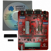
BOARD DEMO DSPICDEM 2
Manufacturer
Microchip Technology
Type
MCUr
Specifications of DM300018
Contents
*
Processor To Be Evaluated
dsPIC30F
Interface Type
RS-232
Silicon Manufacturer
Microchip
Core Architecture
DsPIC
Core Sub-architecture
DsPIC30
Silicon Core Number
DsPIC30F
Silicon Family Name
DsPIC30F2xxx, DsPIC30F3xxx
Lead Free Status / RoHS Status
Not applicable / RoHS Compliant
For Use With/related Products
dsPIC30F
Lead Free Status / Rohs Status
Lead free / RoHS Compliant
Other names
Q2448034
Available stocks
Company
Part Number
Manufacturer
Quantity
Price
Company:

Part Number:
DM300018
Manufacturer:
MICROCHIP
Quantity:
12 000


Hardware
14.1.10 External Connection Headers
Two 40-pin headers, H8 and H9, allow the user to connect hardware external to the
dsPICDEM 2 Development Board into the circuit.
The schematic of the external connection headers is shown in Figure
A-6: “dsPICDEM™ 2 Development Board Schematic (Sheet 5 of 7)”.
14.1.11 Analog Temperature Sensor
Temperature sensor, U5, is a -40°C to +125°C linear output TC1047A connected to
analog channel AN3 of the dsPIC30F device through header H10. The header H10
allows the temperature sensor output to be fed to dsPIC30F devices in the Motor
Control family (M ALL position) or the General Purpose and Sensor family (GP ALL
position). The output of the temperature sensor is fed directly to the dsPIC DSC device.
The output voltage range for the TC1047A is typically 750 mV at +25°C. The TC1047A
exhibits a typical 10 mV/C voltage slope.
The schematic of the temperature sensor is shown in Figure A-6: “dsPICDEM™ 2
Development Board Schematic (Sheet 5 of 7)”
14.1.12 Analog Potentiometer
Potentiometer, R15, is connected to analog channel, AN2, of the dsPIC30F devices via
header H13. The voltage output range for the potentiometer is between 0VDC and V
DD
(+5VDC). The voltage source is provided by VR1 or TP1. The header, H13, allows the
potentiometer output to be fed to dsPIC30F devices in the Motor Control family (M ALL
position) or the General Purpose and Sensor family (GP ALL position)
The schematic of the analog potentiometer circuit is shown in Figure
A-6: “dsPICDEM™ 2 Development Board Schematic (Sheet 5 of 7)”.
14.1.13 Reset Switch
The Reset switch (S1) is connected to the MCLR pin on all device sockets, as well as
the LCD and LCD controller (dsPIC30F2011). The Reset switch circuit is shown in
Figure A-7: “dsPICDEM™ 2 Development Board Schematic (Sheet 6 of 7)”.
© 2005 Microchip Technology Inc.
DS51558A-page 93
Related parts for DM300018
Image
Part Number
Description
Manufacturer
Datasheet
Request
R

Part Number:
Description:
Manufacturer:
Microchip Technology Inc.
Datasheet:
Part Number:
Description:
Manufacturer:
Microchip Technology Inc.
Datasheet:
Part Number:
Description:
Manufacturer:
Microchip Technology Inc.
Datasheet:
Part Number:
Description:
Manufacturer:
Microchip Technology Inc.
Datasheet:
Part Number:
Description:
Manufacturer:
Microchip Technology Inc.
Datasheet:
Part Number:
Description:
Manufacturer:
Microchip Technology Inc.
Datasheet:
Part Number:
Description:
Manufacturer:
Microchip Technology Inc.
Datasheet:
Part Number:
Description:
Manufacturer:
Microchip Technology Inc.
Datasheet: