AT91SAM7S-EK Atmel, AT91SAM7S-EK Datasheet
AT91SAM7S-EK
Specifications of AT91SAM7S-EK
Available stocks


Related parts for AT91SAM7S-EK


AT91SAM7S-EK Summary of contents
Page 1
... AT91SAM7S-EK Evaluation Board .............................................................................................. User Guide ...
Page 2
...
Page 3
... Table of Contents Section 1 Overview ............................................................................................... 1-1 1.1 Scope ........................................................................................................1-1 1.2 Deliverables ..............................................................................................1-1 1.3 AT91SAM7S-EK Evaluation Board ...........................................................1-1 Section 2 Setting Up the AT91SAM7S-EK Board................................................. 2-1 2.1 Electrostatic Warning ................................................................................2-1 2.2 Requirements............................................................................................2-1 2.3 Powering Up the Board .............................................................................2-1 2.4 Getting Started ..........................................................................................2-1 2.5 AT91SAM7S-EK Block Diagram ...............................................................2-2 Section 3 Board Description ...
Page 4
... Table of Contents ii 6112C–ATARM–01-Feb-07 AT91SAM7S-EK Evaluation Board User Guide ...
Page 5
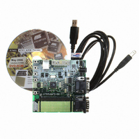
... The AT91SAM7S-EK evaluation board enables the evaluation of and code development for applications running on an AT91SAM7Sxx device. This document describes the evaluation board fitted with an AT91SAM7S256. This guide focuses on the AT91SAM7S-EK board as an evaluation platform for the AT91SAM7S family. The AT91SAM7S-EK package contains the following items: ...
Page 6
... The user can also evaluate the AT91SAM7S32 with this board. A 48-pin TQFP footprint has been provided for this purpose so, the user must unsolder the AT91SAM7S256 microcontroller (IC4) and fit the AT91SAM7S32 on the 48- pin TQFP footprint (IC5). AT91SAM7S-EK Evaluation Board User Guide ...
Page 7
... The AT91SAM7S-EK is not delivered with the JTAG/ICE interface required to start evaluating the device. AT91SAM7S-EK is self-powered by the USB port. If the USB port is not used, the card can be supplied by an external DC power supply via the 2.1 mm socket (J1). The polar- ity of the power supply is not critical. ...
Page 8
... Setting Up the AT91SAM7S-EK Board 2.5 AT91SAM7S-EK Block Diagram 2-2 6112C–ATARM–01-Feb-07 Figure 2-1. Block Diagram for AT91SAM7S-EK Board Analog Inputs 4 User Pushbuttons 1.8V VDDCORE VDDOUT 3.3V Oscillator, PLL 7 - 14V DC Input 5V Power Supply RS232 Driver User LEDs UART AT91SAM7S256 NRST Pushbutton ...
Page 9
... AT91SAM7S256 Microcontroller AT91SAM7S-EK Evaluation Board User Guide ® • Incorporates the ARM7TDMI ARM – High-performance 32-bit RISC Architecture – High-density 16-bit Instruction Set – Leader in MIPS/Watt ™ – EmbeddedICE In-circuit Emulation, Debug Communication Channel Support • 256 Kbytes of Internal High-speed Flash, Organized in 1024 Pages of 256 Bytes – ...
Page 10
... Flash Power Supply – 1.8V VDDCORE Core Power Supply with Brown-out Detector – 3.3V VDDANA Analog Voltage Supply • Fully Static Operation MHz at 1.65V and 85 C Worst Case Conditions • Available in a 64-lead TQFP Package ® Infrared Modulation/Demodulation AT91SAM7S-EK Evaluation Board User Guide ...
Page 11
... AT91SAM7S256 Block Diagram 3.3 Memory 3.4 Clock Circuitry AT91SAM7S-EK Evaluation Board User Guide Figure 3-1. AT91SAM7S256 Block Diagram TDI TDO ICE JTAG TMS SCAN TCK JTAGSEL System Controller TST FIQ AIC IRQ0-IRQ1 PCK0-PCK2 PLLRC PLL PMC XIN OSC XOUT RCOSC ...
Page 12
... All I/Os of the AT91SAM7S256 are routed to this connector. This allows the developer to check the integrity of the components and to extend the features of the board by add- ing external hardware components or boards. This allows the developer to fit additional components for prototyping use. AT91SAM7S-EK Evaluation Board User Guide ...
Page 13
... Configuration Strap AT91SAM7S-EK Evaluation Board User Guide Table 4-1 gives details on configuration straps on the AT91SAM7S-EK evaluation board and their default settings. Table 4-1. Configuration Straps Default Designation Setting JP1 Closed JP2 Closed JP3 Opened JP4 Closed JP5 Opened JP6 Closed ...
Page 14
... Enables the use of the EXT_AD5 (Analog Input 5) Erases all internal Flash memory when the board is powered so, the user must close J28 for at least 10 ms. GND Test point GND Test point GND Test point GND Test point AT91SAM7S-EK Evaluation Board User Guide ...
Page 15
... Schematics AT91SAM7S-EK Evaluation Board User Guide This section contains the following schematics: ! Board Layout And Silkscreen Printing - Top View ! 64-pin SAM7 Microcontroller (dual footprint) ! 48-pin SAM7 Microcontroller ! Power Supply ! ICE/EXT Connectors ! Device Interface ! PIO ! User PAD Grid Section 5 Schematics 5-1 ...
Page 16
...
Page 17
...
Page 18
...
Page 19
...
Page 20
...
Page 21
...
Page 22
...
Page 23
...
Page 24
... Schematics 5-2 6112C–ATARM–01-Feb-07 AT91SAM7S-EK Evaluation Board User Guide ...
Page 25
... Revision History AT91SAM7S-EK Evaluation Board User Guide Table 6-1. Document Comments 6112A First issue. 6112B New schematics. 6112C Corrected features for JP26 and JP27 in “Configuration Straps”. Corrected device label in 64-pin SAM7 schematic. Section 6 Revision History Change Request Ref. 1457 ...
Page 26
... Revision History 6-2 6112C–ATARM–01-Feb-07 AT91SAM7S-EK Evaluation Board User Guide ...
Page 27
... Disclaimer: The information in this document is provided in connection with Atmel products. No license, express or implied, by estoppel or otherwise, to any intellectual property right is granted by this document or in connection with the sale of Atmel products. EXCEPT AS SET FORTH IN ATMEL’S TERMS AND CONDI- TIONS OF SALE LOCATED ON ATMEL’S WEB SITE, ATMEL ASSUMES NO LIABILITY WHATSOEVER AND DISCLAIMS ANY EXPRESS, IMPLIED OR STATUTORY WARRANTY RELATING TO ITS PRODUCTS INCLUDING, BUT NOT LIMITED TO, THE IMPLIED WARRANTY OF MERCHANTABILITY, FITNESS FOR A PARTICULAR PURPOSE, OR NON-INFRINGEMENT ...