AT91SAM7SE-EK Atmel, AT91SAM7SE-EK Datasheet
AT91SAM7SE-EK
Specifications of AT91SAM7SE-EK


Related parts for AT91SAM7SE-EK


AT91SAM7SE-EK Summary of contents
Page 1
... AT91SAM7SE-EK Evaluation Board .............................................................................................. User Guide ...
Page 2
... AT91SAM7SE-EK Evaluation Board User Guide ...
Page 3
... Table of Contents Section 1 Overview............................................................................................... 1-1 1.1 Scope........................................................................................................1-1 1.2 Deliverables ..............................................................................................1-1 1.3 AT91SAM7SE-EK Evaluation Board ........................................................1-1 Section 2 Setting Up the AT91SAM7SE-EK Board .............................................. 2-1 2.1 Electrostatic Warning ................................................................................2-1 2.2 Requirements............................................................................................2-1 2.3 Layout .......................................................................................................2-2 2.4 Powering Up the Board .............................................................................2-3 2.5 Getting Started..........................................................................................2-3 2 ...
Page 4
... Section 5 Schematics ........................................................................................... 5-1 5.1 Schematics ...............................................................................................5-1 Section 6 Errata .................................................................................................... 6-1 6.1 PIO Usage ................................................................................................6-1 6.2 TWI line pullups are too weak for Fast Mode operation............................6-1 Section 7 Revision History.................................................................................... 7-1 7.1 Revision History ........................................................................................7-1 AT91SAM7SE-EK Evaluation Board User Guide ...
Page 5
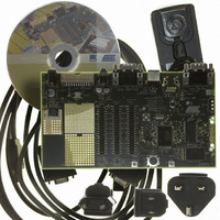
... AT91SAM7SE- EK Evaluation Board AT91SAM7SE-EK Evaluation Board User Guide The AT91SAM7SE-EK evaluation board enables the evaluation of and code develop- ment for applications running on an AT91SAM7SE device. This guide focuses on the AT91SAM7SE-EK board as an evaluation platform. The AT91SAM7SE-EK package contains the following items: ...
Page 6
... Overview 1-2 6241B–ATARM–22-Mar-07 ! One power LED and two general-purpose LEDs ! One joystick and two user input pushbuttons ! One Reset pushbutton ! Three expansion connectors (PIO A, PIO B, PIO C) ! One EBI expansion BGA-like footprint connector AT91SAM7SE-EK Evaluation Board User Guide ...
Page 7
... The board must not be subjected to high electrostatic potentials. A grounding strap or similar protective device should be worn when handling the board. Avoid touching the component pins or any other metallic element. In order to set up the AT91SAM7SE-EK evaluation board, the following items are needed: ! The AT91SAM7SE-EK evaluation board itself. ...
Page 8
... Setting Up the AT91SAM7SE-EK Board 2.3 Layout 2-2 6241B–ATARM–22-Mar-07 Figure 2-1. AT91SAM7SE-EK Layout - Top View AT91SAM7SE-EK Evaluation Board User Guide ...
Page 9
... Getting Started AT91SAM7SE-EK Evaluation Board User Guide Figure 2-2. AT91SAM7SE-EK Layout - Bottom View The AT91SAM7SE-EK requires 5V DC (±5%). DC power is supplied to the board via the 2 5.5 mm socket J1. Coaxial plug center positive standard. The AT91SAM7SE-EK evaluation board is delivered with a CD-ROM containing all nec- essary information and step-by-step procedures for working with the most common development toolchains ...
Page 10
... Setting Up the AT91SAM7SE-EK Board 2.6 AT91SAM7SE-EK Block Diagram POWER SUPPLY PWM0 POWERLED PWM1 USERLED1 PWM2 USERLED2 PB22 RIGHTCLIC PB23 UP PB24 DOWN PB27 LEFT PB26 RIGHT PB25 PUSHLEFTCLIC PCK2 MCLK TD SDIN TF LRFS TK BCLK AT73C213 MISO DOUT MOSI DIN SPCK CLK NPCS1 CS NRST ...
Page 11
... AT91SAM7SE Microcontroller AT91SAM7SE-EK Evaluation Board User Guide ® • Incorporates the ARM7TDMI ARM – High-performance 32-bit RISC Architecture – High-density 16-bit Instruction Set – Leader in MIPS/Watt ™ – EmbeddedICE In-circuit Emulation, Debug Communication Channel Support • Internal High-speed Flash – 512 Kbytes, Organized in Two Contiguous Banks of 1024 Pages of 256 Bytes Dual Plane (AT91SAM7SE512) – ...
Page 12
... Supported – General Call Supported in Slave Mode • One 8-channel 10-bit Analog-to-Digital Converter, Four Channels Multiplexed with Digital I/Os ™ • SAM-BA – Default Boot program – Interface with SAM-BA Graphic User Interface ® Infrared Modulation/Demodulation AT91SAM7SE-EK Evaluation Board User Guide ...
Page 13
... AT91SAM7SE-EK Evaluation Board User Guide ® • IEEE 1149.1 JTAG Boundary Scan on All Digital Pins • Four High-current Drive I/O lines Each • Power Supplies – Embedded 1.8V Regulator, Drawing up to 100 mA for the Core and External Components – 1.8V or 3,3V VDDIO I/O Lines Power Supply, Independent 3.3V VDDFLASH Flash Power Supply – ...
Page 14
... SDRAM Controller PDC PDC Static Memory Controller PDC ECC Controller FIFO USB Device PDC PWMC PDC SSC PDC TWI AT91SAM7SE-EK Evaluation Board User Guide VDDIN GND VDDOUT VDDCORE VDDIO VDDFLASH ERASE PGMRDY PGMNVALID PGMNOE PGMCK PGMM0-PGMM3 PGMD0-PGMD15 PGMNCMD PGMEN0-PGMEN1 D[31:0] A0/NBS0 ...
Page 15
... User Interface 3.10 Debug Interface 3.11 Expansion Slot AT91SAM7SE-EK Evaluation Board User Guide ! 512 Kbytes of Internal Flash ! 32 KBytes of Internal High Speed SRAM ! 32 Mbytes of SDRAM memory (16-bit bus width) ! 256 Mbytes of NANDFlash memory (8-bit bus width) ! 18.432 MHz 20 pF miniature AT cut strip crystal ...
Page 16
... SPI DATAFLASH & Audio DAC (SPCK) Audio DAC AT73C213 (LRFS) Audio DAC AT73C213 (BCLK) Audio DAC AT73C213 (SDIN) ETHERNET DM9000A (Chip Select) SDRAM DEVICE (NBS1) SDRAM DEVICE (SDA10) SDRAM DEVICE (SDCKE) SDRAM DEVICE (Chip Select) SDRAM DEVICE (SDWE) SDRAM DEVICE (CAS) AT91SAM7SE-EK Evaluation Board User Guide ...
Page 17
... PB18 PCK2 PB19 FIQ PB20 IRQ0 PB21 PCK1 PB22 NPCS3 PB23 PWM0 PB24 PWM1 PB25 PWM2 PB26 TIOA2 PB27 TIOB2 PB28 TCLK1 AT91SAM7SE-EK Evaluation Board User Guide Peripheral B Comments RAS D30 D31 Peripheral B Comments A0_NBS0 A1_NBS2 A10 A11 A12 A13 A14 ...
Page 18
... PCK1 PCK2 NPCS1 NCS3_NANDCS NWAIT NANDOE NANDWE NCS7 NWR0_NWE_CFWE NRD_CFOE NCS0 Function Audio DAC AT73C213 (MCLK) Function DATA BUS (PC0..PC15) NandFlash (NANDOE) NandFlash (NANDWE) USB_CNX (VBUS DETECT) and NandFlash (ALE). See errata section NandFlash (CLE) AT91SAM7SE-EK Evaluation Board User Guide ...
Page 19
... Jumpers 4.2 Audio Configuration AT91SAM7SE-EK Evaluation Board User Guide Table 4-1. Jumpers Default Designation Setting J2 Closed J5-1 Opened J5-2 Closed J5-3 Closed J5-4 Closed J5-5 Closed J5-6 Closed Note: 1. These jumpers are provided for power consumption measurement use. By default, they are closed. To use this feature, the user has to open the strap and insert an anmeter ...
Page 20
... Enables the use of Ready Busy signal Disables write protect Enables the use of the Serial DataFlash Disables the write protect. Enables SCL access Enables SDA access Feature Enables the use of the Ethernet controller DM9000A Enables the use of the IRQ Ethernet controller AT91SAM7SE-EK Evaluation Board User Guide ...
Page 21
... Miscellaneous AT91SAM7SE-EK Evaluation Board User Guide Refer to Section 3.12 and top level schematic for details on PIO usage. Table 4-7. Default Designation Setting R4 Soldered R51 Soldered R47 Soldered R48 Soldered R58 Soldered R59 R60 Soldered R61 TP1 N.A TP2 N.A TP3 N ...
Page 22
... Configuration 4-4 6241B–ATARM–22-Mar-07 AT91SAM7SE-EK Evaluation Board User Guide ...
Page 23
... Schematics AT91SAM7SE-EK Evaluation Board User Guide This section contains the following schematics: ! Board Layout And Silkscreen Printing - Top View ! Power & Audio & User Interface ! AT91SAM7SE512-LQFP128 ! Memory ! Ethernet ! Serial Interface ! Expansion Section 5 Schematics 5-1 6241B–ATARM–22-Mar-07 ...
Page 24
... D30 PA31 D31 AT91SAM7SE-EK AT91SAM7SE-EK AT91SAM7SE-EK DIAGRAM DIAGRAM DIAGRAM This agreement is our property. Reproduction and publication without our written authorization shall expose offender to legal proceedings. This agreement is our property. Reproduction and publication without our written authorization shall expose offender to legal proceedings. ...
Page 25
... GND_DAC AT91SAM7SE-EK AT91SAM7SE-EK AT91SAM7SE-EK POWER & AUDIO & UI POWER & AUDIO & UI POWER & AUDIO & UI This agreement is our property. Reproduction and publication without our written authorization shall expose offender to legal proceedings. This agreement is our property. Reproduction and publication without our written authorization shall expose offender to legal proceedings. ...
Page 26
... J5-1 J5-1 VDDFLASH CURRENT MEASURE AT91SAM7SE-EK AT91SAM7SE-EK AT91SAM7SE-EK AT91SAM7SE512-LQFP128 AT91SAM7SE512-LQFP128 AT91SAM7SE512-LQFP128 This agreement is our property. Reproduction and publication without our written authorization shall expose offender to legal proceedings. This agreement is our property. Reproduction and publication without our written authorization shall expose offender to legal proceedings. ...
Page 27
... VSS SERIAL EEPROM AT91SAM7SE-EK AT91SAM7SE-EK AT91SAM7SE-EK MEMORY MEMORY MEMORY This agreement is our property. Reproduction and publication without our written authorization shall expose offender to legal proceedings. This agreement is our property. Reproduction and publication without our written authorization shall expose offender to legal proceedings. ...
Page 28
... R41 R41 LINK&ACT AT91SAM7SE-EK AT91SAM7SE-EK AT91SAM7SE-EK ETHERNET ETHERNET ETHERNET This agreement is our property. Reproduction and publication without our written authorization shall expose offender to legal proceedings. This agreement is our property. Reproduction and publication without our written authorization shall expose offender to legal proceedings. ...
Page 29
... R ADM3202ARNZ ADM3202ARNZ AT91SAM7SE-EK AT91SAM7SE-EK AT91SAM7SE-EK SERIAL INTERFACES SERIAL INTERFACES SERIAL INTERFACES This agreement is our property. Reproduction and publication without our written authorization shall expose offender to legal proceedings. This agreement is our property. Reproduction and publication without our written authorization shall expose offender to legal proceedings. ...
Page 30
... PITCH 100NF 100NF AT91SAM7SE-EK AT91SAM7SE-EK AT91SAM7SE-EK EXPANSION EXPANSION EXPANSION This agreement is our property. Reproduction and publication without our written authorization shall expose offender to legal proceedings. This agreement is our property. Reproduction and publication without our written authorization shall expose offender to legal proceedings. ...
Page 31
... Schematics 5-2 6241B–ATARM–22-Mar-07 AT91SAM7SE-EK Evaluation Board User Guide ...
Page 32
... R29 should be replaced by smaller values (e.g., 2 Note that there is no need to change the pull-up resistors if the TWI is used in Standard Mode (up to 100 Kbits/s). In the schematics (sheet 1/7, ”AT91SAM7SE-EK Diagram”), the MCLK and BCLK sources implementation does not guarantee a correct phase relation as specified in the AT73C213 datasheet. ...
Page 33
... Errata 6-2 6241B–ATARM–22-Mar-07 AT91SAM7SE-EK Evaluation Board User Guide ...
Page 34
... Revision History AT91SAM7SE-EK Evaluation Board User Guide Table 7-1. Document Comments 6241A First issue. Section 6.2 ”TWI line pullups for Fast 6241B Added errata Mode operation” Section 6.3 ”AT73C213 clocking” Added errata Section 7 Revision History . . Change Request Ref. ...
Page 35
... Revision History 7-2 6241B–ATARM–22-Mar-07 AT91SAM7SE-EK Evaluation Board User Guide ...
Page 36
... Disclaimer: The information in this document is provided in connection with Atmel products. No license, express or implied, by estoppel or otherwise, to any intellectual property right is granted by this document or in connection with the sale of Atmel products. EXCEPT AS SET FORTH IN ATMEL’S TERMS AND CONDI- TIONS OF SALE LOCATED ON ATMEL’S WEB SITE, ATMEL ASSUMES NO LIABILITY WHATSOEVER AND DISCLAIMS ANY EXPRESS, IMPLIED OR STATUTORY WARRANTY RELATING TO ITS PRODUCTS INCLUDING, BUT NOT LIMITED TO, THE IMPLIED WARRANTY OF MERCHANTABILITY, FITNESS FOR A PARTICULAR PURPOSE, OR NON-INFRINGEMENT ...