XCARD XC-2 XMOS, XCARD XC-2 Datasheet - Page 10
XCARD XC-2
Manufacturer Part Number
XCARD XC-2
Description
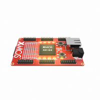
BOARD DEV KIT XS1-G4 ETHERNET
Manufacturer
XMOS
Series
XCore™r
Type
MCUr
Specifications of XCARD XC-2
Design Resources
XC-2 Schematic
Contents
Board, Cable
For Use With/related Products
XS1-G4
Lead Free Status / RoHS Status
Lead free / RoHS Compliant
Other names
880-1014


XMOS
8 Power Connector [D] and Regulator [K]
The XC-2 requires connection from an external 5V power supply. The voltage
is converted by the on-board regulator to the 1V and 3V3 supplies used by the
components.
9 XSYS Connector [H]
The XC-2 includes an XSYS connector, which can be used to boot and debug
code on all of the XS1-G4’s processors. The XSYS connector provides pins for
JTAG control, system reset, processor debug, two UART links and one XMOS
Link. The routing of these I/O pins along with the power pins is shown below.
The XMOS XTAG connector converts between XSYS and USB 2.0, allowing the
XC-2 to be connected to most PCs. On power on, the XS1-G4 boots from the
on-board flash memory. The XS1-G4 can then be put into JTAG mode by the
PC, which then boots another program.
No UART hardware is provided. Instead, two UART pins are mapped to ports,
as shown in the table below.
XC-2 H
ARDWARE
M
ANUAL
PORT_UART_RX
PORT_UART_TX
Pin
X0D22 P1G0 PORT UART RX
X1D23 P1H0 PORT UART TX
SS_DEBUG
SS_RESET
(1.4)
SS_TRST
SS_TDO
SS_TMS
SS_TCK
SS_TDI
3V3
Port
1b
1
19
20
2
3V3
GND
X0D4
GND
X0D5
GND
X0D6
GND
X0D7
GND
Processor
0
H
2009/07/09
9/16
Related parts for XCARD XC-2
Image
Part Number
Description
Manufacturer
Datasheet
Request
R

Part Number:
Description:
BOARD DEV KIT XS1-G4
Manufacturer:
XMOS
Datasheet:

Part Number:
Description:
DEV KIT EVENT-DRIVEN PROC XS1-L1
Manufacturer:
XMOS
Datasheet:

Part Number:
Description:
BOARD KIT XS1-G4 LED CTRL TILE
Manufacturer:
XMOS
Datasheet:

Part Number:
Description:
ADAPTER USB DEBUGGER JTAG XSYS2
Manufacturer:
XMOS
Datasheet:

Part Number:
Description:
BOARD DEV KIT XS1-G4
Manufacturer:
XMOS
Datasheet:

Part Number:
Description:
IC MPU 32BIT SINGLE CORE 64LQFP
Manufacturer:
XMOS
Datasheet:

Part Number:
Description:
IC MPU 32BIT SINGLE CORE 64LQFP
Manufacturer:
XMOS
Datasheet:
Part Number:
Description:
IC MPU 32BIT SINGLE CORE 64LQFP
Manufacturer:
XMOS
Datasheet:

Part Number:
Description:
IC MPU 32BIT SINGLE CORE 64LQFP
Manufacturer:
XMOS
Datasheet:
Part Number:
Description:
IC MPU 32BIT SINGLE CORE 64LQFP
Manufacturer:
XMOS
Datasheet:

Part Number:
Description:
IC MPU 32BIT SINGLE CORE 128TQFP
Manufacturer:
XMOS
Datasheet:
Part Number:
Description:
IC MPU 32BIT SINGLE CORE 64LQFP
Manufacturer:
XMOS
Datasheet:
Part Number:
Description:
IC MPU 32BIT SINGLE CORE 128TQFP
Manufacturer:
XMOS
Datasheet:
Part Number:
Description:
IC MPU 32BIT SINGLE CORE 128TQFP
Manufacturer:
XMOS
Datasheet:

Part Number:
Description:
IC MPU 32BIT DUAL CORE 124QFN
Manufacturer:
XMOS
Datasheet: