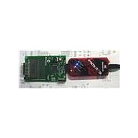
DM164130-1 Microchip Technology, DM164130-1 Datasheet - Page 29

DM164130-1
Manufacturer Part Number
DM164130-1
Description
BOARD EVAL PICKIT PIC16LF1937
Manufacturer
Microchip Technology
Series
PICkit™r
Type
MCUr
Datasheet
1.DM164130-1.pdf
(42 pages)
Specifications of DM164130-1
Contents
Board
Processor To Be Evaluated
PIC16LF1937
Processor Series
PICxxF1xxx
Data Bus Width
8 bit
Operating Supply Voltage
1.8 V to 3.6 V
Silicon Manufacturer
Microchip
Core Architecture
PIC
Core Sub-architecture
PIC16
Silicon Core Number
PIC16F
Silicon Family Name
PIC12F1xxx, PIC16F1xxx
Lead Free Status / RoHS Status
Lead free / RoHS Compliant
For Use With/related Products
PIC16LF1937
Lead Free Status / Rohs Status
Lead free / RoHS Compliant
Available stocks
Company
Part Number
Manufacturer
Quantity
Price
Company:
Part Number:
DM164130-1
Manufacturer:
Microchip Technology
Quantity:
135
Company:
Part Number:
DM164130-10
Manufacturer:
MICROCHIP
Quantity:
12 000
6.1
6.2
© 2009 Microchip Technology Inc.
INTRODUCTION
COMMON PROBLEMS
There may come a time when you need to determine why your F1 Evaluation Platform
is not performing correctly. This chapter lists a few of the problems that can prevent
proper operation.
6.2.1
Make sure there is no shorting jumper at JP3. Then, go back and review Chapter
2. “Getting Started” of this manual.
6.2.2
The demo code in supplied with your F1 Evaluation Platform uses the Timer1 oscillator
to drive the LCD. If the Timer1 oscillator is not oscillating, the LCD will remain blank.
Here are some steps to assure that your Timer1 oscillator is working properly.
1. Clean and dry the board especially around the components at the top right corner
2. Make sure no foreign material is shorting the crystal leads.
3. If you are using the RC0 and RC1 pins for some other function, you should
The Timer1 oscillator of the PIC16LF1937 is a very low-power design that can be easily
disrupted by stray leakage. In an actual application, Microchip recommends that the
crystal circuit be conformal coated to prevent leakage. Please review Application Note
AN1288, “Design Practices for Low-Power External Oscillators” for more information.
6.2.3
The BLDC start-up algorithm could be having trouble finding the BEMF zero-crossing
signal required to synchronize the motor commutation.
If you have attached the BLDC add-on board and you are using the supplied BLDC
motor, then the pot labeled iRef needs to be turned completely counter clockwise to
assure that a good BEMF zero-crossing signal is detected by the PIC16LF1937.
If you are using a different motor, you need to adjust the zero-crossing threshold to
match the requirements of the motor. For more information, consult the documentation
supplied with the BLDC add-on board.
of the PIC16LF1937.
modify lcd_init to reconfigure the LCD peripheral for a different clock
source.
Chapter 6. Troubleshooting
The board will not power up
LCD is blank, but everything else works
The motor spins, but then stops
F1 EVALUATION PLATFORM
USER’S GUIDE
DS41401A-page 29


