DM163030 Microchip Technology, DM163030 Datasheet - Page 47
DM163030
Manufacturer Part Number
DM163030
Description
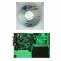
KIT DEV PICDEM LCD2
Manufacturer
Microchip Technology
Series
PICDEM™r
Type
MCUr
Specifications of DM163030
Contents
Evaluation Board
Processor To Be Evaluated
PIC18F85J90
Interface Type
RS-232
Lead Free Status / RoHS Status
Lead free / RoHS Compliant
For Use With/related Products
PIC18F8493
Lead Free Status / Rohs Status
Lead free / RoHS Compliant
Available stocks
Company
Part Number
Manufacturer
Quantity
Price
Company:

Part Number:
DM163030
Manufacturer:
MICROCHIP
Quantity:
12 000


A.6
A.7
A.8
A.9
A.10 ANALOG INPUT
2010 Microchip Technology Inc.
OSCILLATOR OPTIONS
RS-232 SERIAL PORT
REAL-TIME CLOCK
SERIAL EEPROM
The on-board firmware uses the internal RC oscillator running at 8 MHz.
• Internal RC oscillator running at 8 MHz can be used.
• Pads provided for user-furnished crystal/resonator (Y2) and two capacitors
• Socket provided for a canned oscillator (Y3). This oscillator can be disabled by
• 32.768 kHz (watch-type) crystal for Timer1 (Y1) is always connected to RC0 and
An RS-232 level shifting IC has been provided with all necessary hardware to support
connection of an RS-232 host through the DB9 connector (PI). The port is configured
as DCE and can be connected to a PC using a serial cable.
This circuit allows the user to configure a PIC microcontroller for timekeeping using a
32.768 kHz clock crystal connected to Timer1 module’s T1OSO and T1OSI pins.
A socket for a Microwire EEPROM is provided on the board to illustrate usage of
the Synchronous mode of operation of the USART module. For its operation:
• Jumpers, JP15 and JP16, should be connected.
• In the jumper, J6, U9-CS should be connected with RB5.
• In the jumper, J13, U9-ORG (pin 6) should be connected to GND.
A 10 k potentiometer is connected through a series of 100 resistors to AN0. The
potentiometer can be adjusted from V
connecting the potentiometer to AN0.
(C16 and C17).
removing jumpers, JP9, JP11 and JP12.
RC1.
Note 1:
2:
3:
For the PIC18F85J90 and PIC18F87J90 PIM, the RG2 and RG3 pins are
connected to RC3 and RC4 of U1A, respectively.
For the PIC16F917 PIM, the RD1 and RD2 pins are connected to RC3
and RC4 of U1A, respectively.
For the PIC18F8490, PIC16F946 and PIC16F/LF/1946/7 PIMs, the RC3
and RC4 pins are connected to RC3 and RC4 of U1A, respectively.
Board Technical Information
CC
to GND. The jumper, J11, should be
DS51662C-page 47
Related parts for DM163030
Image
Part Number
Description
Manufacturer
Datasheet
Request
R

Part Number:
Description:
Manufacturer:
Microchip Technology Inc.
Datasheet:
Part Number:
Description:
Manufacturer:
Microchip Technology Inc.
Datasheet:
Part Number:
Description:
Manufacturer:
Microchip Technology Inc.
Datasheet:
Part Number:
Description:
Manufacturer:
Microchip Technology Inc.
Datasheet:
Part Number:
Description:
Manufacturer:
Microchip Technology Inc.
Datasheet:
Part Number:
Description:
Manufacturer:
Microchip Technology Inc.
Datasheet:
Part Number:
Description:
Manufacturer:
Microchip Technology Inc.
Datasheet:
Part Number:
Description:
Manufacturer:
Microchip Technology Inc.
Datasheet: