ATSTK526 Atmel, ATSTK526 Datasheet - Page 19
ATSTK526
Manufacturer Part Number
ATSTK526
Description
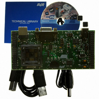
KIT STARTER FOR AT90USB82/162
Manufacturer
Atmel
Series
AVR®r
Type
MCUr
Specifications of ATSTK526
Contents
Starter Kit Board, Power Supply, Cable and Software
Processor To Be Evaluated
AT90USB82/162
Data Bus Width
8 bit
Interface Type
RS-232, USB
Silicon Manufacturer
Atmel
Core Architecture
AVR
Silicon Core Number
AT90USB82, AT90USB162
Kit Contents
Board Docs
Rohs Compliant
Yes
For Use With/related Products
AT90USB162, AT90USB82
For Use With
ATSTK500 - PROGRAMMER AVR STARTER KIT
Lead Free Status / RoHS Status
Lead free / RoHS Compliant


7709B–AVR–07/08
Using the STK526
2.7.3
2.7.4
2.8
2.8.1
2-18
Main Clock from STK500
RESET from STK500
In-System Programming
Programming with USB bootloader: DFU (Device Firmware Upgrade)
Figure 2-21 . EXP.CON 0 and EXP.CON 1 Connectors
The AVR clock frequency (external) coming from STK500 (XT1/XT2) can also be
controlled from AVR Studio®.
The AVR RESET coming from STK500 (NRST - EXP.CON 0) can also control the
STK526.
AT90USB82/162 part comes with a default factory pre-programmed USB bootloader
located in the on-chip boot section of the AT90USB82/162. This is the easiest and
fastest way to reprogram the device directly over the USB interface. The “Flip” PC-
based application offers a flexible and user friendly interface to reprogram the
application over the USB bus.
The HWB pin of the AT90USB82/162 allows to force the bootloader execution after
reset. (Please refer to AT90USB82/162 datasheet section “Bootloader support”). To
force bootloader execution, operate as follows:
“STKX1” and ”STKX2” jumpers should be closed
Press both “RST” and “HWB” push buttons
First release the “RST” push button
Then release the “HWB” push button
n.c. (AUXI0)
n.c. (CT7)
n.c. (CT5)
n.c. (CT3)
n.c. (CT1)
NRST
GND
GND
GND
PG1
VTG
PC7
PC5
PC3
PC1
PA7
PA5
PA3
PA1
n.c.
EXP. CON 0
13 14
15 16
17 18
19 20
21 22
23 24
25 26
27 28
29 30
31 32
33 34
35 36
37 38
39 40
11 12
1 2
3 4
5 6
7 8
9 10
GND
n.c. (AUXO0)
n.c. (CT6)
n.c. (CT4)
n.c. (CT2)
n.c. (BSEL2)
REF
PG2
PG0
GND
VTG
PC6
PC4
PC2
PC0
PA6
PA4
PA2
PA0
GND
Top View
n.c. (DATA7)
n.c. (DATA5)
n.c. (DATA3)
n.c. (DATA1)
n.c. (AUXI1)
n.c. (SCK)
n.c. (SI)
GND
GND
GND
VTG
PB7
PB5
PB3
PB1
PD7
PD5
PD3
PD1
XT1
EXP. CON 1
STK526 rev. B Hardware User Guide
13 14
15 16
17 18
19 20
21 22
23 24
25 26
27 28
29 30
31 32
33 34
35 36
37 38
39 40
11 12
1 2
3 4
5 6
7 8
9 10
GND
n.c. (AUXO1)
n.c. (DATA6)
n.c. (DATA4)
n.c. (DATA2)
n.c. (DATA0)
n.c. (SO)
n.c. (CS)
XT2
VTG
GND
PB6
PB4
PB2
PB0
PD6
PD4
PD2
PD0
GND
Related parts for ATSTK526
Image
Part Number
Description
Manufacturer
Datasheet
Request
R

Part Number:
Description:
DEV KIT FOR AVR/AVR32
Manufacturer:
Atmel
Datasheet:

Part Number:
Description:
INTERVAL AND WIPE/WASH WIPER CONTROL IC WITH DELAY
Manufacturer:
ATMEL Corporation
Datasheet:
Part Number:
Description:
Low-Voltage Voice-Switched IC for Hands-Free Operation
Manufacturer:
ATMEL Corporation
Datasheet:
Part Number:
Description:
MONOLITHIC INTEGRATED FEATUREPHONE CIRCUIT
Manufacturer:
ATMEL Corporation
Datasheet:
Part Number:
Description:
AM-FM Receiver IC U4255BM-M
Manufacturer:
ATMEL Corporation
Datasheet:
Part Number:
Description:
Monolithic Integrated Feature Phone Circuit
Manufacturer:
ATMEL Corporation
Datasheet:
Part Number:
Description:
Multistandard Video-IF and Quasi Parallel Sound Processing
Manufacturer:
ATMEL Corporation
Datasheet:
Part Number:
Description:
High-performance EE PLD
Manufacturer:
ATMEL Corporation
Datasheet:
Part Number:
Description:
8-bit Flash Microcontroller
Manufacturer:
ATMEL Corporation
Datasheet:
Part Number:
Description:
2-Wire Serial EEPROM
Manufacturer:
ATMEL Corporation
Datasheet: