AT91EB55 Atmel, AT91EB55 Datasheet - Page 10
AT91EB55
Manufacturer Part Number
AT91EB55
Description
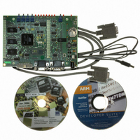
KIT EVAL FOR ARM AT91M55800A
Manufacturer
Atmel
Series
AT91SAM Smart ARMr
Type
MCUr
Datasheet
1.AT91EB55.pdf
(40 pages)
Specifications of AT91EB55
Contents
Evaluation Board, Cable, Power Jack, CD-ROM
For Use With/related Products
AT91M55800A
Lead Free Status / RoHS Status
Contains lead / RoHS non-compliant
Available stocks
Company
Part Number
Manufacturer
Quantity
Price


1709C–ATARM–28-Apr-05
Setting Up the AT91EB55 Evaluation Board
2.4
2.5
2.6
2.7
2-2
Jumper Settings
Powering Up the
Board
Measuring
Current
Consumption on
the
AT91M55800A
Testing the
AT91EB55
Evaluation Board
JP1 is used to boot on standard or user programs. For standard operations, set it in the
STD position.
JP8 is used to select the core power supply of the AT91M55800A. Operations at 2V are
not supported on the current silicon.
For more information about jumpers and other straps, see Appendix A.
DC power is supplied to the board via the 2.1 mm socket (J1) shown below in Figure 2-
2. The polarity of the power supply is not critical. The minimum voltage required is 7V.
Figure 2-2. 2.1 mm Socket
The board has a voltage regulator providing +3.3V. The regulator allows the input volt-
age to be from 7V to 12V. When you switch the power on, the red LED marked
“POWER” will light up. If it does not, switch off and check the power supply connections.
The battery BT1 provides a 3V power supply to the Advanced Power Management Con-
troller and the Real Time Clock (V
first close the JP9 jumper.
The board is designed to generate the power for the AT91 product only through the
jumpers JP5 (V
ments to be made on the current consumption of the AT91 product. See Appendix A for
further details.
In order to test the AT91EB55 Evaluation board, the following procedure should be
performed:
1. Hold down the SW1 button and power up the board or generate a reset and wait
2. Release the SW1 button. The LEDs D1 to D7 light up in sequential order. If an
The LEDs represent the following devices:
! D1 for the internal SRAM
! D2 for the external SRAM
for the light sequence on each LED to complete. All the LEDs light once and the
D1 LED remains lit.
error is detected, all the LEDs will light up twice.
DDIO
), JP8 (V
positive (+)
or
negative (-)
DDCORE
DDBU
) and JP9 (V
). In order to power up this module, the user must
2.1 mm connector
AT91EB55 Evaluation Board User Guide
DDBU
). This feature enables measure-
Related parts for AT91EB55
Image
Part Number
Description
Manufacturer
Datasheet
Request
R

Part Number:
Description:
DEV KIT FOR AVR/AVR32
Manufacturer:
Atmel
Datasheet:

Part Number:
Description:
INTERVAL AND WIPE/WASH WIPER CONTROL IC WITH DELAY
Manufacturer:
ATMEL Corporation
Datasheet:
Part Number:
Description:
Low-Voltage Voice-Switched IC for Hands-Free Operation
Manufacturer:
ATMEL Corporation
Datasheet:
Part Number:
Description:
MONOLITHIC INTEGRATED FEATUREPHONE CIRCUIT
Manufacturer:
ATMEL Corporation
Datasheet:
Part Number:
Description:
AM-FM Receiver IC U4255BM-M
Manufacturer:
ATMEL Corporation
Datasheet:
Part Number:
Description:
Monolithic Integrated Feature Phone Circuit
Manufacturer:
ATMEL Corporation
Datasheet:
Part Number:
Description:
Multistandard Video-IF and Quasi Parallel Sound Processing
Manufacturer:
ATMEL Corporation
Datasheet:
Part Number:
Description:
High-performance EE PLD
Manufacturer:
ATMEL Corporation
Datasheet:
Part Number:
Description:
8-bit Flash Microcontroller
Manufacturer:
ATMEL Corporation
Datasheet:
Part Number:
Description:
2-Wire Serial EEPROM
Manufacturer:
ATMEL Corporation
Datasheet: