EVAL-ADUC7028QSZ Analog Devices Inc, EVAL-ADUC7028QSZ Datasheet
EVAL-ADUC7028QSZ
Specifications of EVAL-ADUC7028QSZ


Related parts for EVAL-ADUC7028QSZ


EVAL-ADUC7028QSZ Summary of contents
Page 1
... One Technology Way • P.O. Box 9106 • Norwood, MA 02062-9106, U.S.A. • Tel: 781.329.4700 • Fax: 781.461.3113 • www.analog.com ADuC7028 Evaluation Board Reference Guide MicroConverter® ADuC7028 Development System by Michael Looney Rev Page AN-904 APPLICATION NOTE ...
Page 2
... S1-5 VIN− ......................................................................................6 S1-6 VIN+ ......................................................................................6 S1-7 ADC4 .....................................................................................6 S1-8 LED.........................................................................................6 External Connectors .........................................................................7 Analog I/O Connector J3 .............................................................7 Power Supply Connector J5 .........................................................7 Emulation Connector J4...............................................................7 Serial Interface Connector J1.......................................................7 Digital I/O Connector J2..............................................................7 Potentiometer Demonstration Circuit ...........................................9 Schematic and Artwork ................................................................. 10 ADuC7028 Evaluation Board Parts List...................................... 12 Rev Page ...
Page 3
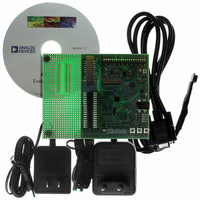
... EVALUATION BOARD OVERVIEW The ADuC7028 evaluation board has the following features: • 2-layer PCB (4 in × form factor). • power supply regulated to 3 board. • 4-pin UART header to connect to RS-232 interface cable. • 20-pin standard JTAG connector. • Demonstration circuit. • ...
Page 4
... This can be used to initiate an external interrupt 0. To enter serial download mode, the user must pull the P0.0/BM pin low while reset is toggled. On the evaluation board, serial download mode can be easily initiated by holding down the serial download push button (S2) while pressing and releasing the reset button (S3) as shown in Figure 1 ...
Page 5
... LED is turned on and when P4.2 is set, the LED is turned off. ANALOG I/O CONNECTIONS All analog I/O connections are brought out on Header J3. ADC0 and ADC1 are buffered using an AD8606 to evaluate single-ended and pseudo differential mode. A potentiometer can be connected to the input of the ADC0 buffer. ...
Page 6
AN-904 DIP SWITCH LINK OPTIONS S1-1 VREF Function Connects the output of the 2.5 V external reference (ADR291) to the V pin (Pin B5) of the ADuC7028. REF Use Slide S1-1 to the on position to connect the external reference ...
Page 7
... Connector J5 allows for connection between the evaluation board and the 9 V power supply provided in the ADuC7028 development system. EMULATION CONNECTOR J4 Connector J4 provides a connection of the evaluation board to the PC via a JTAG emulator. SERIAL INTERFACE CONNECTOR J1 Connector J1 provides a simple connection of the evaluation board to the PC via a serial port cable provided with the ADuC7028 development system ...
Page 8
AN-904 Table 3. Pin Functions for Digital I/O Connector J2 Pin No. Pin Function J2-1 DGND J2-2 P4.5 PLAO[13] J2-3 P4.4 PLAO[12] J2-4 P4.3 PLAO[11] J2-5 P4.2 PLAO[10] J2-6 P1.0 T1/SPM0/PLAI[0] J2-7 P1.1 SPM1/PLAI[1] J2-8 P1.2 SPM2/PLAI[2] J2-9 P1.3 CTS/SDA1/PLAI[3] ...
Page 9
POTENTIOMETER DEMONSTRATION CIRCUIT Using the sample code in pot.c located in the code example folder, the variation in the potentiometer resistance can be seen on the output LED. Note that the internal and external reference are 2.5 V, which gives ...
Page 10
... AN-904 SCHEMATIC AND ARTWORK Figure 3. Evaluation Board Schematic Rev Page 06682-004 ...
Page 11
... Figure 4. Evaluation Board Silkscreen Rev Page AN-904 ...
Page 12
... AN-904 ADuC7028 EVALUATION BOARD PARTS LIST Table 4. Qty Component 1 EVAL-ADuC7028QS QuickStart PCB 4 PCB Stand-off S2, S3 D1, D2 C1, C5, C13, C15, C18, C22, C23 2 C9, C10 9 C2, C3, C4, C6, C12, C14, C16, C17, C24 2 C7 C11, C19 2 C20, C21 R5, R6, R8 R10, R11 3 R12, R18 R20 ...