101-0678 Rabbit Semiconductor, 101-0678 Datasheet - Page 75
101-0678
Manufacturer Part Number
101-0678
Description
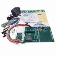
KIT DEV RABBITCORE/RCM3600
Manufacturer
Rabbit Semiconductor
Series
RabbitCore 3000r
Type
MPU Moduler
Datasheet
1.20-101-0673.pdf
(136 pages)
Specifications of 101-0678
Rohs Status
RoHS non-compliant
Contents
RabbitCore Module, Dev. Board, AC Adapter, Cable and Dynamic C® CD-Rom
Processor To Be Evaluated
RCM3600
For Use With/related Products
RCM3600
Lead Free Status / Rohs Status
Lead free / RoHS Compliant
Other names
316-1037


B.1.1 Prototyping Board Features
•
•
•
•
•
•
•
•
•
User’s Manual
Power Connection
Note that the 3-pin header is symmetrical, with both outer pins connected to ground and
the center pin connected to the raw DCIN input. The cable of the AC adapter provided
with the North American version of the Development Kit ends in a plug that connects
to the power-supply header, and can be connected to the 3-pin header in either orienta-
tion. A similar header plug leading to bare leads is provided for overseas customers.
Users providing their own power supply should ensure that it delivers 7.5–30 V DC at
500 mA. The voltage regulators will get warm while in use.
Regulated Power Supply
input jack is routed to a 5 V switching voltage regulator, then to a separate 3.3 V linear
regulator. The regulators provide stable power to the RCM3600 module and the Proto-
typing Board.
Power LED
Board.
Reset Switch
RCM3600’s
I/O Switches and LEDs
nected to the PF4 and PB7 pins of the RCM3600 module and may be read as inputs by
sample applications.
Two LEDs are connected to the PF6 and PF7 pins of the RCM3600 module, and may
be driven as output indicators by sample applications.
Prototyping Area
of through-hole components. +3.3 V, +5 V, and Ground buses run at both edges of this
area. Several areas for surface-mount devices are also available. (Note that there are
SMT device pads on both top and bottom of the Prototyping Board.) Each SMT pad is
connected to a hole designed to accept a 30 AWG solid wire.
LCD/Keypad Module
in directly to headers LCD1JA, LCD1JB, and LCD1JC. The signals on headers
LCD1JB and LCD1JC will be available only if the LCD/keypad module is plugged in
to header LCD1JA. Appendix C provides complete information for mounting and using
the LCD/keypad module.
Module Extension Headers
module is duplicated at header J3. Developers can solder wires directly into the appro-
priate holes, or, for more flexible development, a 2 x 20 header strip with a 0.1" pitch
can be soldered into place. See Figure B-4 for the header pinouts.
Analog I/O Shrouded Headers
Prototyping Board is available on shrouded headers J8 and J9. See Figure B-4 for the
header pinouts.
—The power LED lights whenever power is connected to the Prototyping
/RESET_IN
—A momentary-contact, normally open switch is connected directly to the
—A generous prototyping area has been provided for the installation
—A 3-pin header is provided for connection to the power supply.
—Rabbit Semiconductor’s LCD/keypad module may be plugged
pin. Pressing the switch forces a hardware reset of the system.
—Two momentary-contact, normally open switches are con-
—The raw DC voltage provided at the POWER IN power-
—The complete non-analog pin set of the RCM3600
—The complete analog pin set of the RCM3600
69
Related parts for 101-0678
Image
Part Number
Description
Manufacturer
Datasheet
Request
R

Part Number:
Description:
COMPUTER SNGLBD BL2101 A/D 0-10V
Manufacturer:
Rabbit Semiconductor
Part Number:
Description:
CARD D/A 0-10V SR9400 SMARTSTAR
Manufacturer:
Rabbit Semiconductor
Datasheet:
Part Number:
Description:
CARD A/D 0-10V SR9300 SMARTSTAR
Manufacturer:
Rabbit Semiconductor
Datasheet:

Part Number:
Description:
WiFi / 802.11 Modules & Development Tools WIRELESS CONTROL APP KIT
Manufacturer:
Rabbit Semiconductor

Part Number:
Description:
KIT DEV RABBITCORE RCM3750
Manufacturer:
Rabbit Semiconductor
Datasheet:
Part Number:
Description:
KIT DEV RABBIT 2000 INT'L
Manufacturer:
Rabbit Semiconductor
Datasheet:
Part Number:
Description:
KIT DEV RABBIT RCM2000 INT'L
Manufacturer:
Rabbit Semiconductor
Datasheet:

Part Number:
Description:
KIT DEVELOPMENT RCM3700 INT'L
Manufacturer:
Rabbit Semiconductor
Datasheet:

Part Number:
Description:
BL4S200 TOOL KIT
Manufacturer:
Rabbit Semiconductor
Datasheet:
Part Number:
Description:
MODULE RABBITCORE RCM3720
Manufacturer:
Rabbit Semiconductor
Datasheet:
Part Number:
Description:
MODULE RABBITCORE RCM3220
Manufacturer:
Rabbit Semiconductor
Datasheet:
Part Number:
Description:
MODULE RABBITCORE RCM3210
Manufacturer:
Rabbit Semiconductor
Datasheet:
Part Number:
Description:
COMPUTER SGL-BOARD OP6600 W/SRAM
Manufacturer:
Rabbit Semiconductor
Datasheet:
Part Number:
Description:
COMPUTER SGL-BD BL2000 SRAM/FLSH
Manufacturer:
Rabbit Semiconductor