101-1108 Rabbit Semiconductor, 101-1108 Datasheet - Page 43
101-1108
Manufacturer Part Number
101-1108
Description
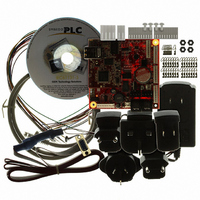
KIT EMBEDDED PLC APPLICATION
Manufacturer
Rabbit Semiconductor
Series
Coyoter
Type
MPU Moduler
Datasheet
1.101-1108.pdf
(70 pages)
Specifications of 101-1108
Contents
BL2500, ISaGRAF V3.50, Embedded PLC software kernel, ISaGRAF Programming Cable and Documentation
Processor To Be Evaluated
Rabbit 3000
Interface Type
RS-232, Ethernet
For Use With/related Products
BL2500
Lead Free Status / RoHS Status
Contains lead / RoHS non-compliant
Other names
316-1120


EMBEDDED
The A/D converter programs DA0 using a successive-approximation binary search until DA0 equals the
A/D converter input voltage. That programmed DA0 voltage is then reported as the A/D converter value.
The A/D converter transforms the voltage at DA0 into a 13.2 mV window around DA0. Because the A/D
converter circuit uses a 13.2 mV window, the accuracy is ±6.6 mV. DA0 can range from 0.1 V to 3.1 V,
which represents 227 steps of 13.2 mV. This represents a resolution of approximately 8 bits. Since the
D/A converter is able to change the DA0 output in 3.22 mV steps, there are 930 steps over the range
from 0.1 V to 3.1 V. This represents a resolution of approximately 10 bits.
The A/D converter has no reference voltage. There is a relative accuracy between measurements, but no
absolute accuracy without calibration. This is because the +3.3 V supply can vary ±5%, the pulse-width
modulated outputs might not reach the full 0 V and 3.3 V rails out of the Rabbit 3000 microprocessor, and
the gain resistors used in the circuit have a 1% tolerance. For these reasons, each BL2500 needs to be
calibrated individually, with the constants held in software, to be able to rely on an absolute accuracy. The
BL2500 has this calibration support.
An A/D conversion takes approximately 83 ms.
4.4 ANALOG OUTPUT
Two D/A converter outputs, DA0 and DA1, are supplied on the BL2500. These are shown in Figure 8.
The D/A converters have no reference voltage. Although they may be fairly accurate from one
programmed voltage to the next, they do not have absolute accuracy. This is because the +3.3 V supply
can change ±5%, the PWM outputs might not achieve the full 0 V and 3.3 V rail out of the processor, and
OEM Technology Solutions
Note:
Only DA1 is available for
PLC BL2500 User’s Manual
Figure 7: Schematic Diagram of the A/D Converter
Figure 8: Schematic Diagram of D/A Converters
EMBEDDED
PLC BL2500 as DA0 is used by the A/D converter.
Hardware Reference
Page 37
Related parts for 101-1108
Image
Part Number
Description
Manufacturer
Datasheet
Request
R

Part Number:
Description:
KIT DEV FOR BL2500 COYOTE
Manufacturer:
Rabbit Semiconductor
Datasheet:

Part Number:
Description:
KIT APPLICATION SIMPLE SENSOR
Manufacturer:
Rabbit Semiconductor
Datasheet:

Part Number:
Description:
KIT DEV RABBITCORE RCM3750
Manufacturer:
Rabbit Semiconductor
Datasheet:

Part Number:
Description:
KIT DEV RABBIT 2000 INT'L
Manufacturer:
Rabbit Semiconductor
Datasheet:
Part Number:
Description:
KIT DEV RABBIT RCM2000 INT'L
Manufacturer:
Rabbit Semiconductor
Datasheet:

Part Number:
Description:
KIT DEVELOPMENT RCM3700 INT'L
Manufacturer:
Rabbit Semiconductor
Datasheet:

Part Number:
Description:
BL4S200 TOOL KIT
Manufacturer:
Rabbit Semiconductor
Datasheet:


Part Number:
Description:
KIT DEVELOPMENT FOR JACKRABBIT
Manufacturer:
Rabbit Semiconductor
Part Number:
Description:
MODULE RABBITCORE RCM3720
Manufacturer:
Rabbit Semiconductor
Datasheet:
Part Number:
Description:
MODULE RABBITCORE RCM3220
Manufacturer:
Rabbit Semiconductor
Datasheet:
Part Number:
Description:
MODULE RABBITCORE RCM3210
Manufacturer:
Rabbit Semiconductor
Datasheet:
Part Number:
Description:
COMPUTER SGL-BOARD OP6600 W/SRAM
Manufacturer:
Rabbit Semiconductor
Datasheet:
Part Number:
Description:
COMPUTER SGL-BD BL2000 SRAM/FLSH
Manufacturer:
Rabbit Semiconductor