STEVAL-IFD001V1 STMicroelectronics, STEVAL-IFD001V1 Datasheet
STEVAL-IFD001V1
Specifications of STEVAL-IFD001V1


Related parts for STEVAL-IFD001V1


STEVAL-IFD001V1 Summary of contents
Page 1
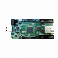
... Introduction This user manual provides a hardware description of both versions of the STR9 Dongle: STEVAL-IFD001V1 (full version) STEVAL-IFD001V2 (lite version) Figure 1. STR9 DONGLE (STEVAL-IFD001V2) This document contains all the necessary assembly information to designers interested in using STR9 Dongle including the block diagram, board schematics, footprints and PCB layouts as well as the bill of materials and any additional assembly instructions ...
Page 2
Contents Contents 1 STR9 Dongle . . . . . . . . . . . . . . . . . . . . . . . . . . . . . . . . . . . ...
Page 3
UM0282 1 STR9 Dongle 1.1 Block diagram This board is based on an which provides calculation power up to 90MIPS. STR912FAW34, STR912FAW42 and STR912FAW44 are referred to STR912FAWxx throughout the document. Figure 2. STR9 Dongle block diagram Power JTAG 4 ...
Page 4
STR9 Dongle 1.2 Schematics Figure 3. Schematics 4/19 P47 P97 P47 124 P46 P96 P46 125 P45 P95 P45 126 P44 P94 P44 127 P43 P93 P43 128 P42 P92 P42 1 P41 P91 P41 2 P40 ...
Page 5
UM0282 Figure 4. Schematics GND 9 GND 7 GND INH 3 3 STR9 Dongle 5/19 ...
Page 6
STR9 Dongle Figure 5. Schematics Note: Refer to Section 1.2.1 on page 8 6/19 10K 2 1 R88 max. 8mA - P6x 10K 2 1 R87 10K 2 1 R86 10K 2 1 R85 for pin connections ...
Page 7
UM0282 Figure 6. Schematics Iref PHY_CLK 12 STR9 Dongle GNDA 24 GNDA 20 GNDA 14 GNDA 10 GNDA VCCA 17 VCCA 16 VCCA 13 ...
Page 8
STR9 Dongle 1.2.1 Pin connections The following tables show the pin connections for the three connectors ANALOG_CON (CN5), DIGITAL_CON (CN4) and EXTENDED_CON (CN3). These are shown in page 6. Table 1. Analog connector, ANALOG_CON (CN5) Pin P40 In/Out P41 In/Out ...
Page 9
UM0282 Table 3. Extended connector, EXTENDED_CON (CN3) Pin P90 In/Out P91 In/Out P92 In/Out P93 In/Out P94 In/Out P30 In/Out P95 In/Out P31 In/Out P32 In/Out P33 In/Out P96 In/Out P34 In/Out P97 In/Out P35 In/Out P36 In/Out P37 In/Out ...
Page 10
STR9 Dongle 1.4 Used footprints www.koala.cz: CM5032 10/19 www.koala.cz: MC-146 www.coilcraft.com: 0603PS-332KLC UM0282 ...
Page 11
UM0282 1.5 PCB layout Figure 7. Top view STR9 Dongle 11/19 ...
Page 12
STR9 Dongle Figure 8. Bottom view 12/19 UM0282 ...
Page 13
UM0282 1.6 Bill of materials Table 4. Chips Part Package U1 LQFP128 U7 TQFP64 U71 SOT23-6L U9 SO8 Table 5. Capacitors Part C114, C115, C116, C117 C707, C708 C30, C40, C50 C03 C02 C61 C07, C09, C714-C715, C85-C88 C05, C118, ...
Page 14
STR9 Dongle Table 7. Resistors Part R709, R20 R62-R63 R707, R708 R710 R90 R714, R716 R84 R82, R83, R81, R04 R67, R713, R715 R02 R711, R712, R717, R03 R01 R102, R64 R719, R721-R729, R91, R85-R88, R21-R28 R101, R61 R65 R66 ...
Page 15
UM0282 Table 9. Power Part Package PW01 SO8cool PW02 DPAK Table 10. Buttons Part B11, B85-B88 - Table 11. Transistors Part Package T1,T2 SOT23-3 Table 12. LEDs & diodes & tranzils Part D01, D03 D02 D04 LD01, LD81 LD82, LD83 ...
Page 16
STR9 Dongle 1.7 Assembling instructions Table 14. JTAG with IAR Part R21 R24, R25 R27, R28 R20 Table 15. Configuration with STE101P Part R710 R707. R708 R709 R721-R725 R726-R729 1.7.1 Assembling of resistors The marking (from top to bottom) is ...
Page 17
UM0282 Assembling instructions for lite version 1.8 CAN transceiver U9 – not assembled Connectors CN3, CN4, CN5, CN9 – not assembled Crystal X2 – use this one GM: 131-082 (Q32.768KHZM) 1.9 Application hints 1.9.1 Ethernet interface Clock input The clock ...
Page 18
... Document revision history Date 19-Jan-2007 24-May-2007 19-June-2007 18/19 Revision 1 Initial release. 2 Section 1.9: Application hints Figure 1: STR9 DONGLE (STEVAL-IFD001V2) Root part numbers changed from STR912FW42xx and 3 STR912FW44x to STR912FAW34, STR912FAW42 and STR912FAW44 throughout the document. Table 4: Chips updated. UM0282 Changes added. updated. ...
Page 19
... UM0282 Information in this document is provided solely in connection with ST products. STMicroelectronics NV and its subsidiaries (“ST”) reserve the right to make changes, corrections, modifications or improvements, to this document, and the products and services described herein at any time, without notice. All ST products are sold pursuant to ST’s terms and conditions of sale. ...