DEMO9S08LL16 Freescale Semiconductor, DEMO9S08LL16 Datasheet
DEMO9S08LL16
Specifications of DEMO9S08LL16
Available stocks


Related parts for DEMO9S08LL16

DEMO9S08LL16 Summary of contents
Page 1
... DEMO9S08LL16 Demonstration Board for Freescale MC9S08LL16 USER GUIDE Email: support@axman.com Support: www.axman.com ...
Page 2
CAUTIONARY NOTES ..............................................................................................................4 TERMINOLOGY.........................................................................................................................4 FEATURES ................................................................................................................................5 REFERENCES ...........................................................................................................................6 GETTING STARTED..................................................................................................................6 MEMORY MAP ..........................................................................................................................6 SOFTWARE DEVELOPMENT...................................................................................................7 DEVELOPMENT SUPPORT ......................................................................................................7 INTEGRATED BDM .............................................................................................................. 7 BDM OPTION HEADERS ................................................................................................. 7 BDM_PORT HEADER........................................................................................................... 8 POWER ...
Page 3
Figure 1: JP1 Option Header ......................................................................................................7 Figure 2: JP1 Option Header ......................................................................................................8 Figure 3: BDM_PORT Header....................................................................................................8 Figure 4: V_SEL ...
Page 4
... EMC Information on the DEMO9S08LL16 board: a) This product as shipped from the factory with associated power supplies and cables, has been verified to meet with requirements of CE and the FCC as a CLASS A product. ...
Page 5
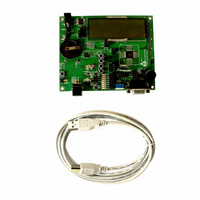
... FEATURES The DEMO9S08LL16 is a demonstration board for the MC9S08LL16 microcontroller. Application development is quick and easy with the integrated USB-BDM, sample software tools, and examples. An optional BDM_PORT port is also provided to allow use of a BDM_PORT cable. Two, 40-pin connectors provide access to all IO signals on the target MCU. • ...
Page 6
... DEMO9S08LL16 _SCH_A.pdf DEMO9S08LL16_Silk_A.pdf LL16_Demo_Board4.zip GETTING STARTED To get started quickly, please refer to the DEMO9S08LL16 Quick Start Guide. This quick start will illustrate connecting the board to a PC, installing the correct version of CodeWarrior Development Studio, and running a simple LED test program. MEMORY MAP The table below shows the default memory map for the MC9S08LL16 immediately out of reset. ...
Page 7
... Multilink BDM and a 6-pin interface header (BDM_PORT). The BDM_PORT header allows connecting a HCS12/HCS08 BDM cable. Integrated BDM The DEMO9S08LL16 board features an integrated USB-Multilink BDM from P&E Microcomputer Systems. The integrated USB-Multilink BDM supports application development and debugging via background debug mode. ...
Page 8
... NOTE: This header is not installed in default configuration. POWER The DEMO9S08LL16 provides several methods to apply power to the board. header allows selection between the various power inputs. For application development and debug, the board may be powered from the USB BDM. The 2.0mm PWR connector supports stand-alone operation and higher power requirements ...
Page 9
The V_SEL option header combines the V_SEL option header and the VDD_EN option header into a single option block. ...
Page 10
... Consult the MC9S08LL16 reference manual for details LVD operation. TIMING The DEMO9S08LL16 internal timing source is active from RESET by default. An external 32 kHz XTAL oscillator, configured for low-power operation, is also provided. Refer to the MC9S08LL16 Data Sheet for details on configuring the selected timing source. ...
Page 11
RS-232 An RS-232 translator provides RS-232 to TTL/CMOS logic level translation on the COM connector. The COM connector is a 9-pin Dsub, right-angle connector. A ferrite bead on shield ground provides ...
Page 12
... The integrated USB-BDM provides a serial link from the target MCU to the host PC through the host application. Refer to the P&E Multilink documentation for further details. LCD The DEMO9S08LL16 provides an 8x24 LCD connected directly to the target MCU. The target MCU provides internal charge-pump and regulated LCD reference. trimmable under MCU control. ...
Page 13
... Potentiometer The DEMO9S08LL16 target board provides a 5K ohm potentiometer (POT) to simulate analog input. The POT is decoupled to minimize noise during adjustment. The figure below shows the USER enable position and associated signal for the potentiometer. The following table shows the connections for each user I/O device. ...
Page 14
... User LED’s The DEMO9S08LL16 target board provides 8, green, LEDs for output indication. Each LED is configured for active-low operation. A series, current-limit resistor prevents excessive diode current. The figure below shows the USER enable position and associated signal for each user LED. ...
Page 15
MCU I/O PORT The MCU I/O PORT connectors (J1 and J2) provide access to the MC9S08LL16 I/O signals. The ...