DK-DEV-4SE530N Altera, DK-DEV-4SE530N Datasheet - Page 22
DK-DEV-4SE530N
Manufacturer Part Number
DK-DEV-4SE530N
Description
KIT DEV STRATIX IV FPGA 4SE530
Manufacturer
Altera
Series
Stratix® IVr
Type
FPGAr
Datasheet
1.DK-DEV-4SE530N.pdf
(54 pages)
Specifications of DK-DEV-4SE530N
Contents
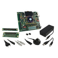
Board, Cables, CD, DVD, Power Supply
Silicon Manufacturer
Altera
Core Architecture
FPGA
Core Sub-architecture
Stratix
Silicon Core Number
EP4S
Silicon Family Name
Stratix IV E
Rohs Compliant
Yes
For Use With/related Products
EP4SE530
Lead Free Status / RoHS Status
Lead free / RoHS Compliant
Other names
544-2605
Available stocks
Company
Part Number
Manufacturer
Quantity
Price


4–6
Table 4–4. Jumper Settings (Part 2 of 2)
Stratix IV E FPGA Development Kit User Guide
J7
J10
J11
J15
J18
J21
J28
Reference
Board
f
QDRII DRIVE
MAXII_JTAG_EN
SHUNT=1.8V QDR
HSMA_JTAG_EN
SHUNT=1.8V RLD
VCC_VCCL_SEL
RLD_ZQ_IMPED
Board
Label
For more information about the FPGA board settings, refer to the
Development Board Reference
The QDR II impedance drive jumper has the following options:
■
■
■
Always keep one and only one shunt installed. Other configurations
might cause damage to the device.
The MAX II JTAG enable jumper has the following options:
■
■
The QDR II VDDQ voltage select jumper has the following options:
■
■
The HSMC port A JTAG enable jumper has the following options:
■
■
The RLDRAM II VDDQ voltage select jumper has the following options:
■
■
The VCC VCCL select jumpers have the following options:
■
■
■
Always keep a shunt installed on pins 1 and 2 only. The current version
of the Stratix IV E device requires 0.9 V.
To use the RLDRAM II impedance drive jumpers, set the mode
register. When the mode register is not set, the RLDRAM II output
impedance is 50 Ω. The RLDRAM II impedance drive jumpers have the
following options:
■
■
■
Installing more than one shunt might cause damage to the device.
Installing the shunt on pins 1 and 2 sets the QDR II output
impedance to the minimum value possible.
Installing the shunt on pins 3 and 4 sets the QDR II output
impedance to 50 Ω.
Installing the shunt on pins 5 and 6 sets the QDR II output
impedance to 60 Ω.
Installing the shunt includes the MAX II EMP2210 device in the
JTAG chain.
Removing the shunt removes the MAX II device from the JTAG
chain.
Installing the shunt sets QDR II VDDQ to 1.8 V.
Removing the shunt sets QDR II VDDQ to 1.5 V.
Installing the shunt includes HSMC port A in the JTAG chain.
Removing the shunt removes HSMC port A from the JTAG chain.
Installing the shunt sets RLDRAM II VDDQ to 1.8 V.
Removing the shunt sets RLDRAM II VDDQ to 1.5 V.
Installing the shunt on pins 1 and 2 sets VCC and VCCL to 0.9 V.
Installing the shunt on pins 2 and 3 sets VCC and VCCL to 1.1 V.
Removing the shunt sets VCC and VCCL to 0.6 V.
Installing the shunt on pins 1 and 2 sets the RLDRAM II output
impedance to the maximum value possible.
Installing the shunt on pins 3 and 4 sets the RLDRAM II output
impedance to 50 Ω.
Installing the shunt on pins 5 and 6 sets the RLDRAM II output
impedance to 60 Ω.
Manual.
Function
Chapter 4: Development Board Setup
© May 2010 Altera Corporation
Factory Default Switch Settings
Stratix IV E FPGA
Shunt Position
Not installed
Not installed
Not installed
Not installed
pins 3 and 4
pins 1 and 2
Installed on
Installed on
Installed
Default
Related parts for DK-DEV-4SE530N
Image
Part Number
Description
Manufacturer
Datasheet
Request
R

Part Number:
Description:
KIT DEV ARRIA II GX FPGA 2AGX125
Manufacturer:
Altera
Datasheet:

Part Number:
Description:
KIT DEV CYCLONE III LS EP3CLS200
Manufacturer:
Altera
Datasheet:

Part Number:
Description:
KIT DEV FPGA 2AGX260 W/6.375G TX
Manufacturer:
Altera
Datasheet:

Part Number:
Description:
KIT DEV MAX V 5M570Z
Manufacturer:
Altera
Datasheet:

Part Number:
Description:
KIT DEV STRATIX V FPGA 5SGXEA7
Manufacturer:
Altera
Datasheet:

Part Number:
Description:
KIT DEVELOPMENT STRATIX III
Manufacturer:
Altera
Datasheet:

Part Number:
Description:
KIT DEVELOPMENT STRATIX IV
Manufacturer:
Altera
Datasheet:

Part Number:
Description:
KIT DEV ARRIA GX 1AGX60N
Manufacturer:
Altera
Datasheet:
Part Number:
Description:
KIT STARTER CYCLONE IV GX
Manufacturer:
Altera
Datasheet:
Part Number:
Description:
KIT DEVELOPMENT STRATIX IV
Manufacturer:
Altera
Datasheet:

Part Number:
Description:
CPLD, EP610 Family, ECMOS Process, 300 Gates, 16 Macro Cells, 16 Reg., 16 User I/Os, 5V Supply, 35 Speed Grade, 24DIP
Manufacturer:
Altera Corporation
Datasheet:
Part Number:
Description:
CPLD, EP610 Family, ECMOS Process, 300 Gates, 16 Macro Cells, 16 Reg., 16 User I/Os, 5V Supply, 15 Speed Grade, 24DIP
Manufacturer:
Altera Corporation
Datasheet: