DM163035 Microchip Technology, DM163035 Datasheet
DM163035
Specifications of DM163035


Related parts for DM163035

DM163035 Summary of contents
Page 1
... Microchip Technology Inc. PICDEM™ Lab Development Board User’s Guide DS41369A ...
Page 2
... PowerMate, PowerTool, REAL ICE, rfLAB, Select Mode, Total Endurance, WiperLock and ZENA are trademarks of Microchip Technology Incorporated in the U.S.A. and other countries. SQTP is a service mark of Microchip Technology Incorporated in the U.S.A. All other trademarks mentioned herein are property of their respective companies. ...
Page 3
... PICDEM Lab Development Board Setup for GPIO Input Labs ................. 38 3.4.4 Lab 5: Adding a Push Button ..................................................................... 39 3.4.5 Lab 6: Push Button Interrupt ..................................................................... 48 3.4.6 Lab 7: Push Button Interrupt-on-Change .................................................. 53 3.4.7 Lab 8: Using Weak Pull-Ups ..................................................................... 58 © 2009 Microchip Technology Inc. ™ PICDEM LAB DEVELOPMENT BOARD USER’S GUIDE ...
Page 4
... Lab 3: Higher Resolution Sensor Readings Using a Single Comparator ...68 Chapter 5. Analog-to-Digital Converter Peripheral Labs 5.1 Introduction ................................................................................................... 75 5.2 ADC Labs ..................................................................................................... 75 5.2.1 Reference Documentation .........................................................................75 5.2.2 Equipment Required ..................................................................................75 5.2.3 Lab 1: Simple ADC ....................................................................................76 5.2.4 Lab 2: Audible Temperature Sensor ..........................................................85 Appendix A. Schematic A.1 PICDEM Lab Development Kit Schematic ................................................... 91 DS41369A-page iv © 2009 Microchip Technology Inc. ...
Page 5
... Chapter 2. “Getting Started” • Chapter 3. “General Purpose Input/Output Labs” • Chapter 4. “Comparator Peripheral Labs” • Chapter 5. “Analog-to-Digital Converter Peripheral Labs” • Appendix A. “Schematic” © 2009 Microchip Technology Inc. TM PICDEM LAB DEVELOPMENT BOARD USER’S GUIDE ...
Page 6
... Optional arguments mcc18 [options] file [options] Choice of mutually exclusive errorlevel {0|1} arguments selection Replaces repeated text var_name [, var_name...] Represents code supplied by void main (void) user { ... } © 2009 Microchip Technology Inc. Examples ® IDE User’s Guide ...
Page 7
... Business of Microchip – Product selector and ordering guides, latest Microchip press releases, listing of seminars and events, listings of Microchip sales offices, distributors and factory representatives © 2009 Microchip Technology Inc. Preface ® IDE installation directory. The Readme files DS41369A-page 3 ...
Page 8
... Local sales offices are also available to help customers. A listing of sales offices and locations is included in the back of this document. Technical support is available through the web site at: http://support.microchip.com DOCUMENT REVISION HISTORY Revision A (February 2009) • Initial Release of this Document. DS41369A-page 4 © 2009 Microchip Technology Inc. ...
Page 9
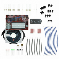
... Diodes • (2) 0.1μF Capacitors • (2) 1μF Capacitors • (2) 10μF Capacitors • (4) Push buttons • (10) 5” Jumper Wires • (10) 3” Jumper Wires © 2009 Microchip Technology Inc. TM PICDEM LAB DEVELOPMENT BOARD USER’S GUIDE Chapter 1. Overview ® ...
Page 10
... To use the PICkit™ Serial Analyzer, connect to appropriate PIC MCU expansion header using jumper wires from receptacle. DS41369A-page 6 ® IDE and HI-TECH C PICDEM™ LAB DEVELOPMENT BOARD ® microcontroller socket U5 ® microcontroller socket U3 ® microcontroller socket U2 ® PRO for the PIC10/12/ © 2009 Microchip Technology Inc. ...
Page 11
... TARGET POWER The PICDEM™ Lab Development Board can be powered in one of three ways: 1. Using a 9-12 V (MIcrochip part #AC162039 recommended) Ensure that connect/disconnect jumper place. © 2009 Microchip Technology Inc. 1 supply to PIC16F690 MCU in socket DD 2 supply to PIC16F819 MCU in socket DD 3 supply to PIC10F206 MCU in socket ...
Page 12
... PIC DD DD ™ 2 PROGRAMMER/DEBUGGER ® microcontrollers populating sockets U5, U3 and U2 have their own ® microcontroller populating U2. ® microcontroller populating U3. ® microcontroller populating U5. ® microcon- ® microcontroller ® microcontroller ® microcontroller potentiometer (R1) to control DD ® micro- © 2009 Microchip Technology Inc. ...
Page 13
... The solderless prototyping area contains a variety of strips under the perforated plastic block. These strips “short” vertical rows of holes together as shown in Figure 1-3. FIGURE 1-3: © 2009 Microchip Technology Inc. CONNECTING THE PICkit™ PROGRAMMER/DEBUGGER TO AN ICSP™ CONNECTOR PICkit™ Programmer/Debugger Denotes Pin 1 ICSP™ ...
Page 14
... TM PICDEM Lab Development Board User’s Guide NOTES: DS41369A-page 10 © 2009 Microchip Technology Inc. ...
Page 15
... Notice the Initialize() is called only once while the remaining functions are executed repeatedly. This method organizes the embedded firmware application into a logic sequence of events: © 2009 Microchip Technology Inc. TM PICDEM LAB DEVELOPMENT BOARD USER’ ...
Page 16
... The following steps outline how to download the latest version of the MPLAB IDE and ® HI-TECH C PRO for the PIC10/12/16 MCU Families compiler strongly recom- mended that all open programs and applications are closed to expedite the installation process. SD41369A-page 12 TYPICAL SOFTWARE CONTROL LOOP MAIN() USED IN LABS © 2009 Microchip Technology Inc. ...
Page 17
... During the installation process, the user will be prompted to install the free HI-TECH C the user install the compiler at this point. Select Yes to launch the installer. In the installer window, click Next to continue. (See Figure 2-3.) © 2009 Microchip Technology Inc. MPLAB ZIP FILE Tools x.xx Installation window should now be open. Click Next> to ® ...
Page 18
... In the next window, select any components in addition to the HI-TECH C the PIC10/12/16 MCU Family Compiler to install (additional components are not required to complete the labs in this user's guide) and click Next to continue. (See Figure 2-5.) SD41369A-page 14 HI TECH INSTALLER WINDOW HI TECH LICENSE AGREEMENT ® Pro for © 2009 Microchip Technology Inc. ...
Page 19
... The installation process will now begin. 15. Once the installation is complete, a confirmation window will open. Select or de-select the Read quick start guide now? radio button and click Finish to proceed. (See Figure 2-7.) © 2009 Microchip Technology Inc. HI TECH COMPONENTS HI TECH LANGUAGE PREFERENCES Getting Started ...
Page 20
... Lab folders must be installed to the C used by the MPLAB IDE. Note: SD41369A-page 16 HI TECH INSTALL CONFIRMATION ® Tools Install Shield Wizard Complete window should soon open ® IDE and HI-TECH C PRO for the PIC10/12/16 MCU Family Lite Mode ® PRO for the © 2009 Microchip Technology Inc. ...
Page 21
... Lab 3: Simple Delays Using Timer0 - Lab 4: Rotate LEDs • Input Labs: - Lab 5: Adding a Push Button - Lab 6: Push Button Interrupt - Lab 7: Push Button Interrupt-on-Change - Lab 8: Using Weak Pull-ups © 2009 Microchip Technology Inc. TM PICDEM LAB DEVELOPMENT BOARD USER’S GUIDE ® microcontrollers have multiple GPIO ...
Page 22
... PICDEM LAB SCHEMATIC FOR GPIO OUTPUT LABS RC5 RC0 6 RC4 RC1 7 RC3 RC2 8 RC6 9 RC7 470Ω 470Ω 470Ω 470Ω LED6 LED5 LED4 V SS PRO for the PIC10/12/16 MCU 470Ω 470Ω 470Ω LED3 LED2 LED1 © 2009 Microchip Technology Inc. ...
Page 23
... Therefore, this application will require that these pins be configured as digital by configuring the associated bits in the ANSEL and ANSELH analog select registers. FIGURE 3-2: © 2009 Microchip Technology Inc. General Purpose Input/Output Labs ) or turn the LED OFF when driven low DD ...
Page 24
... Next> to continue. (See Figure 3-3.) FIGURE 3- the Step Two: window, select the HI TECH Universal ToolSuite from the Active Toolsuite drop down menu. The window should now resemble Figure 3-4. DS41369A-page 20 STEP ONE ® IDE. A ® IDE and © 2009 Microchip Technology Inc. ...
Page 25
... Finally, rename the Lab_Template.c file in the right window to GPIO_Lab1.c by clicking on it three times to enable editing the name. The Step Four: window should now resemble Figure 3-6. Click Next> to continue. © 2009 Microchip Technology Inc. General Purpose Input/Output Labs STEP TWO STEP THREE ...
Page 26
... Click Finish to exit the Project Wizard. FIGURE 3-7: 9. The MPLAB visible, it can be opened by selecting View>Project. The Project window should resemble Figure 3-8. DS41369A-page 22 STEP FOUR SUMMARY ® IDE Workspace should now be open. If the Project window is not © 2009 Microchip Technology Inc. ...
Page 27
... TRISC3 = 0;//Make RC3 (pin 7) output TRISC4 = 0;//Make RC4 (pin 6) output TRISC5 = 0;//Make RC5 (pin 5) output TRISC6 = 0;//Make RC6 (pin 8) output TRISC7 = 0;//Make RC7 (pin 9) output © 2009 Microchip Technology Inc. General Purpose Input/Output Labs PROJECT WINDOW INITIALIZE() CODE FOR LAB 1 DS41369A-page 23 ...
Page 28
... PIC16F690 and provide target power. 16. In the MPLAB™ IDE Project Workspace, select Programmer>Select Programmer>PICkit 2. 17. The PICkit 2 Programmer/Debugger toolbar should now be visible in the workspace as shown in Figure 3-9. DS41369A-page 24 DO_OUTPUT() CODE FOR LAB 1 MAIN() CODE FOR LAB 1 © 2009 Microchip Technology Inc. ...
Page 29
... At this rate, the software loop execution needs to be slowed down so that the LED flashing is visible to the eye. This is done using a delay routine within the Timing() functional block called from the main() software control loop as shown in Figure 3-11. © 2009 Microchip Technology Inc. General Purpose Input/Output Labs PICkit 2 PROGRAMMER/DEBUGGER TOOLBAR 1 ...
Page 30
... Configure all PORTC pins as digital outputs DS41369A-page 26 MAIN() SOFTWARE CONTROL LOOP FLOWCHART FOR LAB 2 main() Initialize() Do_Outputs() Timing() TIMING() DELAY ROUTINE FLOWCHART FOR LAB 2 TIMING() Create two 8-bit variables: • delay_var1 = 45571 • delay_var2 = 3 YES delay_var2 - delay_var1 = 45571 NO YES delay_var1 - END © 2009 Microchip Technology Inc. ...
Page 31
... The only change from the previous lab is that the PORTC bits are all set high Copy/paste the code in Example 3-5 over the Do_Outputs() code from the previous lab to accommodate the XOR bit toggle. © 2009 Microchip Technology Inc. General Purpose Input/Output Labs INITIALIZE() CODE FOR LAB 2 ...
Page 32
... Program the PIC16F690. The LEDs connected to the individual PORTC pins should now all flash on/off in 1 second intervals. The solution for this project is located in the C:\PICDEM_Lab\GPIO_Labs\GPIO_Lab2\solution directory. DS41369A-page 28 DO_OUTPUT() CODE FOR LAB 2 TIMING() FOR LAB 2 MAIN() CODE FOR LAB 2 //Software Control Loop © 2009 Microchip Technology Inc. ...
Page 33
... Equation 3-1 to create Equation 3-2. EQUATION 3-2: TMR0 Overflow Period = (4/F Using a 1:32 prescaler setting as an example and a 4 MHz internal oscillator TMR0 Overflow Period = 1 © 2009 Microchip Technology Inc. General Purpose Input/Output Labs 8 = 256 times inclusive then rollover or overflow back to ‘0’. Whenever ...
Page 34
... Equation 3-4. DS41369A-page 30 CALCULATING A TMR0 PRELOAD VALUE TO GENERATE A 10MS OVERFLOW PERIOD ) x (256 - Preload Value) x prescaler OSC μ Second x 64)] DELAY_10MS() USING TIMER0 Delay_10mS() Clear the TMR0 overflow flag (T0IF) Preload TMR0 register with 100 NO T0IF = 0? YES END © 2009 Microchip Technology Inc. ...
Page 35
... Therefore, to implement delays greater than 65.5mS, a counter variable is implemented as shown in the flowchart of Figure 3-14 for a 1 second delay. FIGURE 3-14: counter variable value determined as follows: 1 second/65.5mS = 15.25 or rounded down to 15 © 2009 Microchip Technology Inc. General Purpose Input/Output Labs MAXIMUM TMR0 OVERFLOW PERIOD ) x 256 x prescaler OSC ...
Page 36
... Timer0 to overflow while (T0IF == 0); ++counter Copy/paste the code in Example 3-9 into the Initialize() over the code from the previous lab. DS41369A-page 32 /4) as the TMR0 register clock source OSC /4 OSC DELAY_1S() CODE FOR LAB 3 15) /4 OSC © 2009 Microchip Technology Inc. ...
Page 37
... More in-depth tutorials on the Timer0 peripheral are covered in “Timers: Note: Timer0 Tutorial (Part 1)” (5162a.pdf) and “Timers: Timer0 Tutorial (Part 2)” (51702a.pdf) files included on the PICDEM™ Lab Development Kit CD. © 2009 Microchip Technology Inc. General Purpose Input/Output Labs INITIALIZE() CODE FOR LAB 3 //FOSC/4 as the clock source ...
Page 38
... MAIN() SOFTWARE CONTROL LOOP FLOWCHART FOR LAB 4 main() Initialize() Decide() Do_Outputs() Timing() DECIDE() FLOWCHART FOR LAB 4 Decide() LED_Output variable initialize to 0b00000001 in Initialize() YES LED_Output = 0b10000000 or LED_Output = 0b00000000 ? NO Shift contents of LED_Output variable left by 1 bit position END LED_Output = 0b00000001 © 2009 Microchip Technology Inc. ...
Page 39
... Timer0 - Use the internal instruction clock (F - Increment TMR0 register on low-to-high transition Assign the prescaler to Timer0 and configure to increment on every 256th transition of F • Initialize the LED_Output variable to ‘0’ © 2009 Microchip Technology Inc. General Purpose Input/Output Labs RESULTS OF DO_OUTPUT() PORTC 0 0 ...
Page 40
... Timer0 prescaler to increment //TMR0 every 256 FOSC/4 clock transitions PS0 = 1; PS1 = 1; PS2 = 1; //Initialize LED_Output to all zeros LED_Output = 0b00000000; DS41369A-page 36 LED_OUTPUT VARIABLE DECLARATION FOR LAB 4 INITIALIZE() CODE FOR LAB 4 //FOSC/4 as the clock source //FOSC/4 transition //Timer0 © 2009 Microchip Technology Inc. ...
Page 41
... Decide(); //Make any decisions Do_Outputs(); //Perform any outputs Timing();//Sets execution rate of the } Compile the project. There should be no errors. © 2009 Microchip Technology Inc. General Purpose Input/Output Labs DECIDE()CODE FOR LAB 4 DO_OUTPUTS() CODE FOR LAB 4 MAIN() CODE FOR LAB 4 ...
Page 42
... Assorted jumper wires 3.4.3 PICDEM Lab Development Board Setup for GPIO Input Labs The GPIO input labs will require that the PICDEM Lab Development Board be configured as shown in Figure 3-12 using the components listed in the previous section. DS41369A-page 38 resistors © 2009 Microchip Technology Inc. ...
Page 43
... Also, switch contacts are not perfectly smooth. As the contacts move against each other, the imperfections and impurities on the surfaces cause the electrical connection to be interrupted. The result is switch bounce. The consequences © 2009 Microchip Technology Inc. General Purpose Input/Output Labs PICDEM LAB SCHEMATIC FOR GPIO INPUT LABS ...
Page 44
... This is a global variable that will be manipulated by the new Get_Inputs() and used to determine PORTC shift direction by the Decide(). DS41369A-page 40 MAIN() SOFTWARE CONTROL LOOP FLOWCHART FOR LAB 5 main() Initialize() Get_Inputs() Decide() Loop Forever Do_Outputs() Timing the TMR0 clock source. OSC OSC /4. © 2009 Microchip Technology Inc. ...
Page 45
... Delay_5mS() to allow any switch bouncing to set- tle. The Delay_5mS() is based off of the Timer0 peripheral as discussed in Lab 3. The software flowchart for Delay_5mS() is shown in Figure 3-21. © 2009 Microchip Technology Inc. General Purpose Input/Output Labs (high or ‘1’ (low or ‘ ...
Page 46
... DELAY_5MS() SOFTWARE FLOWCHART FOR LAB 5 Delay_5mS() /4 (4MHz/4) clock OSC Clear the Timer0 overflow flag (T0IF) Preload the Timer0 result register (TMR0) with 100 T0IF = 1 (i.e., TMR0 overflow) ? END ) x number of counts to overflow x prescaler OSC 5mS = 99.75 rounded to 100 1μSeconds YES © 2009 Microchip Technology Inc. ...
Page 47
... Copy/paste the code in section marked: //--------------------DATA MEMORY---------------------- EXAMPLE 3-16: unsigned char LED_Output;//Variable used to set/clear PORTC bits bit direction;//Variable to select direction of shifting LEDs © 2009 Microchip Technology Inc. General Purpose Input/Output Labs DECIDE() SOFTWARE FLOWCHART FOR LAB 5 Decide() YES direction = 0 ...
Page 48
... T0IF = 0; //preload the TMR0 register TMR0 = 100; //Sit here and wait for Timer0 to overflow while (T0IF == 0 Copy/paste the code in Example 3-18 into the Initialize() over the code from the previous lab. DS41369A-page 44 DELAY_5MS() CODE FOR LAB 5 © 2009 Microchip Technology Inc. ...
Page 49
... PS1 = 0; PS2 = 1; //Initialize the direction flag to shift bits from //right-to-left //(i. Shift PORTC bits from right-to-left // direction = 0; //Initialize LED_Output to all zeros LED_Output = 0b00000000; © 2009 Microchip Technology Inc. General Purpose Input/Output Labs INITIALIZE() FOR GPIO LAB Shift PORTC bits from left-to-right DS41369A-page 45 ...
Page 50
... LED_Output = 0b00000001; //If neither of these conditions are true, simply shift //the LED_Output variable's contents to the Right by 1 //bit position else LED_Output <<=1; } DS41369A-page 46 GET_INPUTS() CODE FOR GPIO LAB 5 //direction bit DECIDE() CODE FOR GPIO LAB 5 © 2009 Microchip Technology Inc. ...
Page 51
... The next labs will remedy these issues through the use of interrupts. The solution for this project is located in the C:\PICDEM_Lab\GPIO_Labs\GPIO_Lab5\solution directory. © 2009 Microchip Technology Inc. General Purpose Input/Output Labs TIMING() CODE FOR GPIO LAB 5 MAIN() CODE FOR LAB 5 ...
Page 52
... The OPTION register features the Interrupt Edge Select (INTEDG) bit that will be used to indicate the edge transition that will trigger an interrupt. The software flowchart for this lab is shown in Figure 3-23. DS41369A-page 48 © 2009 Microchip Technology Inc. ...
Page 53
... Note the removal of the Get_Inputs() from the previous lab. This code will now be handled by an Interrupt Service Routine (ISR) whenever the push button is pressed. The PB_PressISR() flowchart is shown in Figure 3-24. FIGURE 3-24: © 2009 Microchip Technology Inc. General Purpose Input/Output Labs MAIN() SOFTWARE CONTROL LOOP FLOWCHART FOR GPIO LAB 6 ...
Page 54
... RA2 is 0 delay for 5mS to filter //any switch bounce Delay_5mS(); //Check to see if RA2 is still 0 //If so, toggle the direction bit if(RA2 == 0) direction ^= 1; } //If RA2 is not 0, keep direction value //the same as it was else direction = direction; } DS41369A-page 50 PB_PRESSISR() CODE FOR GPIO LAB 6 © 2009 Microchip Technology Inc. ...
Page 55
... To indicate a function that should be used whenever an interrupt occurs, the Note: interrupt function qualifier is needed. This qualifier is specific to the HI-TECH C 2. Copy/paste the code in Example 3-24 into the Initialize() over the code from the previous lab. © 2009 Microchip Technology Inc. General Purpose Input/Output Labs ® Compiler. DS41369A-page 51 ...
Page 56
... It should be noted that the Global Interrupt Enable bit (GIE) is set last in the Example 3-24. This ensures that interrupts will not occur during the Initialize(), having adverse consequences on code operation. DS41369A-page 52 INITIALIZE() CODE FOR GPIO LAB 6 //transition of RA2 voltage //PIC16F690 ***ALWAYS DONE LAST***** © 2009 Microchip Technology Inc. ...
Page 57
... Each PORTA and PORTB pin is individually configurable as an interrupt-on-change pin. Control bits in the Interrupt-on-Change PORTA register (IOCA) enable or disable the interrupt function for each pin. © 2009 Microchip Technology Inc. General Purpose Input/Output Labs MAIN() CODE FOR GPIO LAB 6 //Software Control Loop ...
Page 58
... RABIE and RABIF bits set Read PORTA RETURN DS41369A-page 54 PB_PRESSISR FLOWCHART FOR LAB 7 YES Clear RABIF flag ? NO RA2 pin = 1 ? Delay for 5mS NO RA2 pin = 1 ? direction = 1 RA2 pin = YES Delay for 5mS NO RA2 pin = 0 ? YES direction = 1 © 2009 Microchip Technology Inc. ...
Page 59
... PROCEDURE Using the firmware developed in the previous lab, make the following changes: 1. Copy/paste the code in Example 3-26 into the PB_PressISR() over the code from the previous lab. © 2009 Microchip Technology Inc. General Purpose Input/Output Labs /4 as clock source OSC /4 clock edge ...
Page 60
... PORTA to latch RA2 value for the next interrupt PORTA = PORTA; 2. Copy/paste the code in Example 3-27 into the Initialize() over the code from the previous lab. DS41369A-page 56 PB_PRESSISR() CODE FOR GPIO LAB 7 © 2009 Microchip Technology Inc. ...
Page 61
... RABIE = 1; //Enable change interrupts RABIF = 0; //Clear the change interrupt flag GIE = 1;//Enable interrupt capability on the //Read PORTA to latch the current RA2 voltage level PORTA = PORTA; © 2009 Microchip Technology Inc. General Purpose Input/Output Labs INITIALIZE() CODE FOR GPIO LAB 7 //PIC16F690 ***ALWAYS DONE LAST***** DS41369A-page 57 ...
Page 62
... PROCEDURE Using the firmware developed in the previous lab, make the following changes: 1. Copy/paste the code in Example 3-28 into the Initialize() over the code from the previous lab. DS41369A-page 58 . Each of the PORTA pins (except RA3) and DD © 2009 Microchip Technology Inc. Ω ...
Page 63
... RABIE = 1; //Enable change interrupts RABIF = 0; //Clear the change interrupt flag GIE = 1;//Enable interrupt capability on the //Read PORTA to latch the current RA2 voltage level PORTA = PORTA; © 2009 Microchip Technology Inc. General Purpose Input/Output Labs INITIALIZE() CODE FOR GPIO LAB 8 //PIC16F690 ***ALWAYS DONE LAST***** DS41369A-page 59 ...
Page 64
... TESTING THE APPLICATION Program the PIC16F690. The application should operate exactly as it did in the previ- ous lab. Only this time with the absence of the 10 K The solution for this project is located in the C:\PICDEM_Lab\GPIO_Labs\GPIO_Lab8\solution directory. DS41369A-page 60 Ω pull-up resistor. © 2009 Microchip Technology Inc. ...
Page 65
... KΩ potentiometer 4. 4 – Light Emitting Diodes 5. 1 – 1N4148 diodes 6. 1 – 1 μF capacitor 7. PIC16F690 populating socket U2 8. Assorted jumper wires © 2009 Microchip Technology Inc. TM PICDEM LAB DEVELOPMENT BOARD USER’S GUIDE ® ® ...
Page 66
... The PICDEM™ Development Board configuration schematic is shown in Figure 4-1. FIGURE 4- The software flowchart for this lab is shown in Figure 4-2. DS41369A-page 62 SCHEMATIC FOR COMPARATOR LAB C1IN+ 18 C12IN0- 17 C1OUT 470Ω LED1 10KΩ R2 10KΩ 100KΩ © 2009 Microchip Technology Inc. ...
Page 67
... C12IN0- pin as the inverting reference C1CH0 = 0; C1CH1 = 0; //Since the comparator 1 output shares the same pin //as PORTA bit 2, configure the corresponding TRISA2 bit //as an output TRISA2 = 0; © 2009 Microchip Technology Inc. Comparator Peripheral Labs MAIN() SOFTWARE CONTROL LOOP FLOWCHART FOR COMPARATOR LAB 1 main() Initialize() Loop Forever ...
Page 68
... The CV • Independent comparator operation • Two 16-level voltage ranges • Ratiometric with V DS41369A-page 64 MAIN() CODE FOR COMPARATOR LAB 1 provides an internally generated REF features: REF DD © 2009 Microchip Technology Inc. ...
Page 69
... Select the low-range feature • Set the CV REF Changes to the PICDEM™ Development Board configuration schematic for this lab are shown in Figure 4-3. © 2009 Microchip Technology Inc. Comparator Peripheral Labs SS Range Selection (VRR) bit in the VRCON (Voltage Reference REF Value Selection bits (VR< ...
Page 70
... Using the firmware developed in the previous lab, make the following changes: 1. Copy/paste the code in Example 4-3 into the Initialize() over the code from the previous lab. DS41369A-page 66 SCHEMATIC FOR COMPARATOR LAB C12IN0- 17 C1OUT 470Ω LED1 100KΩ © 2009 Microchip Technology Inc. ...
Page 71
... Program the PIC16F690. The application should behave exactly as it did in the previous lab with the exception of less components used. The solution for this project is located in the C:\PICDEM_Lab\Comparator_Labs\Comparator_Lab2\solution directory. © 2009 Microchip Technology Inc. Comparator Peripheral Labs INITIALIZE CODE FOR COMPARATOR LAB 2 1; ...
Page 72
... The charge across the capacitor then discharges slowly across the resistor R1. Once the capacitor charge drops below the 0.6V fixed DS41369A-page 68 BASIC RELAXATION OSCILLATOR CIRCUIT PIC16F690 0. C12IN0 C1OUT D1 . Once the Com- DD © 2009 Microchip Technology Inc. ...
Page 73
... R4 470Ω LED1 V SS © 2009 Microchip Technology Inc. Comparator Peripheral Labs τ C), or the time it takes to discharge the τ effectively increasing the frequency of the oscillator. If the resistor /4) as its time base or an external clock source OSC SCHEMATIC FOR COMPARATOR LAB 3 ...
Page 74
... The Interrupt Service Routine, TMR0_ISR(), is shown in Figure 4-7. DS41369A-page 70 MAIN() SOFTWARE CONTROL LOOP FLOWCHART FOR COMPARATOR LAB 3 main() Initialize() Loop Forever Wait output to the non-inverting reference input. REF to route the 0.6V fixed voltage reference to the non-inverting REF /4 as the Timer0 clock source. © 2009 Microchip Technology Inc. ...
Page 75
... Using the firmware developed in the previous lab, make the following changes: 1. Copy/paste the code in Example 4-4 into the top of the main firmware source file under the heading labeled: //----------------INTERRUPT CODE--------------- © 2009 Microchip Technology Inc. Comparator Peripheral Labs TMR0_ISR FLOWCHART FOR COMPARATOR LAB 3 TMR0_ISR() ...
Page 76
... Timer1 register pair TMR1L = 0; TMR1H = 0; //Turn Timer1 back to start counting again TMR1ON = 1; } else PORTC = PORTC Copy/paste the code in Example 4-5 into the Initialize() over the code from the previous lab: DS41369A-page 72 TMR0_ISR CODE FOR LAB 3 © 2009 Microchip Technology Inc. ...
Page 77
... Timer0 Interrupts T0IE = 1; //Clear the Timer0 overflow interrupt flag T0IF = 0; //Preload TMR0 with 10 to keep overflow period //less than Timer1 overflow period TMR0 = 10; //Enable global interrupts GIE = 1; © 2009 Microchip Technology Inc. Comparator Peripheral Labs INITIALIZE CODE FOR COMPARATOR LAB 3 DS41369A-page 73 ...
Page 78
... LED display. Introducing cold to the thermistor should have the opposite effect thereby decreasing the binary count. The solution for this project is located in the C:\PICDEM_Lab\Comparator_Lab\Comparator_Lab3\solution directory DS41369A-page 74 MAIN() CODE FOR COMPARATOR LAB 3 . © 2009 Microchip Technology Inc. ...
Page 79
... – 100 K Ω – – Light Emitting Diodes 8. 1 – IRFD010 N-Channel MOSFET 9. PIC16F690 populating socket U2 10. Assorted jumper wires © 2009 Microchip Technology Inc. TM PICDEM LAB DEVELOPMENT BOARD USER’S GUIDE ® IDE and HI-TECH C resistor resistors resistor resistor Ω ...
Page 80
... ADC result as left justified with the four Most Significant bits of the 10-bit result output to the RC0, RC1,RC2 and RC3 PORTC pins used to light connected LEDs accordingly.The PICDEM™ Development Board configuration schematic is shown in Figure 5-1. DS41369A-page 76 © 2009 Microchip Technology Inc. ...
Page 81
... V The software flowchart for this lab is shown in Figure 5-2. FIGURE 5-2: Global variables initialized: • 8-bit variable LED_output will be used to light the three LEDs connected to PORTC © 2009 Microchip Technology Inc. SCHEMATIC FOR ADC LAB ...
Page 82
... ADC is completed (GO/DONE = 0). Therefore, the Get_Inputs() initiates an ADC by setting GO/DONE then sits and waits for the bit to clear indicating a completed conversion. The software flowchart for the Get_Inputs() is shown in Figure 5-3. DS41369A-page μ Seconds or a fre- © 2009 Microchip Technology Inc. μ Seconds. ...
Page 83
... EXAMPLE 5-1: unsigned char LED_Output = 0;//assigned to PORTC to light 2. Copy/paste the code in Example 5-2 into the top of the main firmware source file under the heading labeled: //----------------SUPPORT ROUTINES--------------- © 2009 Microchip Technology Inc. MAIN() SOFTWARE CONTROL LOOP FLOWCHART FOR COMPARATOR LAB 1 Get_Inputs() Delay_1mS() ...
Page 84
... Delay_1mS(void) { unsigned int delay_var = 98; //Keep looping until the delay_var is // equal to zero (should take 1mS) while(--delay_var Copy/paste the code in Example 5-3 into the Initialize() section labeled: //ADD INITIALIZE CODE HERE DS41369A-page 80 DELAY_1MS() CODE FOR ADC LAB 1 © 2009 Microchip Technology Inc. ...
Page 85
... CHS0 = 0; CHS1 = 1; CHS2 = 0; CHS3 = 1; //Select result format left justified ADFM = 0; //Turn on ADC module ADON = 1; 4. Copy/paste the code in Example 5-4 into the Get_Inputs() section labeled: //ADD GET INPUTS CODE HERE © 2009 Microchip Technology Inc. INITIALIZE CODE FOR COMPARATOR LAB 1 DS41369A-page 81 ...
Page 86
... Initialize(); //Initialize the relevant registers while(1) { Get_Inputs(); Decide(); Do_Outputs(); } 8. Compile the project. There should be no errors. DS41369A-page 82 GET_INPUTS() CODE FOR ADC LAB 1 DECIDE() CODE FOR ADC LAB 1 //to the right D0_OUTPUTS() CODE FOR ADC LAB 1 MAIN() CODE FOR ADC LAB 1 © 2009 Microchip Technology Inc. ...
Page 87
... V for V Example: If following an ADC, the ADRESH:ADRESL contains the following 10-bit value: 10-BIT ADC RESULT (ADRESH: ADRESL 2.5V = Using a 5V reference voltage with a 10-bit provides a resolution of Note: 0.000488V or 4.88mV (5V/1024). © 2009 Microchip Technology Inc. ADC RESULT BIT SIGNIFICANCE used as the ADC reference ...
Page 88
... C:\PICDEM_Lab\ADC_Labs\ADC_Lab1\solution directory. DS41369A-page 84 CORRESPONDING VOLTAGE ON PIN 13 RELATED TO LIT LEDS (1 = LED ON LED OFF) LED3 LED2 LED1 used as DD pin 13 Voltage < 0.3125V > 0.3125V > 0.625V > 0.9375V > 1.25V > 1.5625V > 1.875V > 2.1875V > 2.5V > 2.8125V > 3.125V > 3.4375V > 3.75V > 4.0625V > 4.375V > 4.6875V or greater © 2009 Microchip Technology Inc. ...
Page 89
... In this way, any change in temperature around the thermistor will alter the frequency of the PWM, thereby changing the audible frequency emitted from the speaker. © 2009 Microchip Technology Inc. SCHEMATIC FOR ADC LAB ...
Page 90
... Select result format left justified (10-bit result in ADRESH<7:0> and ADRESL<7:6>). - Turn on ADC module. DS41369A-page 86 MAIN() SOFTWARE CONTROL LOOP FLOWCHART FOR ADC LAB 2 Loop Forever /4 internal instruction clock as the Timer0 clock source. OSC /4) as the TMR0 OSC main() Initialize() Get_Inputs() Decide() Do_Outputs() Timing() /4. OSC © 2009 Microchip Technology Inc. ...
Page 91
... LED_Output = 0; //assigned to PORTC to light bit toggle = 0;//Used to generate waveform on RC0 unsigned char TMR0_preload = 0; //Varied by ADRESH to change 2. Copy/paste the code in Example 5-9 over the Initialize() code from the previous lab: © 2009 Microchip Technology Inc. GLOBAL VARIABLES USE IN ADC LAB 2 //connected LEDs //frequency of //waveform on RC0 ...
Page 92
... ADC input channel Pin 13 (RB4/AN10) CHS0 = 0; CHS1 = 1; CHS2 = 0; CHS3 = 1; //Select result format left justified ADFM = 0; //Turn on ADC module ADON = 1; 3. Copy/paste the code in Example 5-10 over the Get_Inputs() code from the previous lab: DS41369A-page 88 INITIALIZE CODE FOR ADC LAB 2 © 2009 Microchip Technology Inc. ...
Page 93
... TMR0_preload value from 255 and //then use to preload TMR0 TMR0 = 255 – TMR0_preload; //Sit here and wait for TMR0 to overflow while (T0IF == 0); © 2009 Microchip Technology Inc. GET_INPUTS() CODE FOR ADC LAB 2 DECIDE() CODE FOR ADC LAB 2 D0_OUTPUTS() CODE FOR ADC LAB 2 ...
Page 94
... Colder temperature sources applied to the thermistor should reduce the speaker output frequency. The solution for this project is located in the C:\PICDEM_Lab\ADC_Labs\ADC_Lab2\solution directory. DS41369A-page 90 MAIN() CODE FOR ADC LAB 2 © 2009 Microchip Technology Inc. ...
Page 95
... Appendix A. Schematic A.1 PICDEM LAB DEVELOPMENT KIT SCHEMATIC 1N4148WS C6 D4 10uF ADJ 0 270Ω ON PWR S1G D5 © 2009 Microchip Technology Inc. TM PICDEM LAB DEVELOPMENT BOARD USER’S GUIDE 1 J26 2PHDR DS41369A-page 91 ...
Page 96
... Fax: 886-3-572-6459 Taiwan - Kaohsiung Tel: 886-7-536-4818 Fax: 886-7-536-4803 Taiwan - Taipei Tel: 886-2-2500-6610 Fax: 886-2-2508-0102 Thailand - Bangkok Tel: 66-2-694-1351 Fax: 66-2-694-1350 © 2009 Microchip Technology Inc. EUROPE Austria - Wels Tel: 43-7242-2244-39 Fax: 43-7242-2244-393 Denmark - Copenhagen Tel: 45-4450-2828 Fax: 45-4485-2829 France - Paris Tel: 33-1-69-53-63-20 ...