DM163035 Microchip Technology, DM163035 Datasheet - Page 62
DM163035
Manufacturer Part Number
DM163035
Description
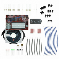
KIT DEVELOPMENT PICDEM LAB
Manufacturer
Microchip Technology
Type
MCUr
Datasheet
1.DM163035.pdf
(96 pages)
Specifications of DM163035
Contents
Board, Cable, Components, CD, PICkit Programmer
Processor To Be Evaluated
PIC10F, PIC12F615, PIC16F616
Data Bus Width
8 bit
Operating Supply Voltage
1.3 V to 5 V
Silicon Manufacturer
Microchip
Core Architecture
PIC
Core Sub-architecture
PIC10, PIC12, PIC16
Silicon Core Number
PIC10F, PIC12F, PIC16F
Silicon Family Name
PIC10F2xx, PIC12F6xx, PIC16F6xx
Lead Free Status / RoHS Status
Lead free / RoHS Compliant
For Use With/related Products
PIC10F206, PIC16F690, PIC16F819
Lead Free Status / Rohs Status
Lead free / RoHS Compliant


PICDEM
DS41369A-page 58
TM
3. All remaining code from the previous lab is unchanged. Compile the project.
3.4.6.4
Program the PIC16F690. The LEDs connected to PORTC should now flash sequen-
tially from left-to-right when the push button is released and flash from right-to-left when
the push button is pressed.
The solution for this project is located in the
C:\PICDEM_Lab\GPIO_Labs\GPIO_Lab7\solution directory.
3.4.7
3.4.7.1
To configure the peripherals used in this lab, the following registers are used:
1. OPTION Register: OPTION (Register 2-2 in Section 2 of the PIC16F690 Data
2. PORTA Weak Pull-Up Register: WPUA (Register 4-5 in Section 4 of the
3.4.7.2
This lab expands on the previous lab by adding weak pull-ups to remove the 10 K
used previously to tie RA2 pin to V
PORTB pins, has an individually configurable internal weak pull-up. Essentially, these
weak pull-ups perform the same task as the resistor connected to the RA2 pin and push
button as shown in Figure 3-12 only internal to the microcontroller. This feature can be
used to decrease component counts in the circuit.
Clearing the PORTA/PORTB Pull-up Enable bit, RABPU, in the OPTION register will
enable weak pull-ups on any PORTA pin selected using the Weak Pull-Up PORTA
register (WPUA).
The only change needed to the PICDEM Lab Development Board Schematic shown in
Figure 3-18 is to remove the 10 KΩ resistor connected to both the push button and pin
RA2.
The Initialize() is all that needs to be changed in firmware by adding the following
configurations:
• Select RA2 to have a weak pull-up by setting the Weak Pull-Up Register bit
• Enable the PORTA/PORTB Pull-up Enable bit (RABPU) in the OPTION register
3.4.7.3
Using the firmware developed in the previous lab, make the following changes:
1. Copy/paste the code in Example 3-28 into the Initialize() over the code
Lab Development Board User’s Guide
- Enables PORTA/PORTB weak pull-ups to be used on the PIC16F690.
- Selects which PORTA pins will have weak pull-ups enabled.
WPUA2 in the WPUA: PORTA Register.
by clearing it.
There should be no errors.
Sheet)
PIC16F690 Data Sheet)
from the previous lab.
TESTING THE APPLICATION
Lab 8: Using Weak Pull-Ups
NEW REGISTERS USED IN THIS LAB
OVERVIEW
PROCEDURE
DD
. Each of the PORTA pins (except RA3) and
© 2009 Microchip Technology Inc.
Ω
Related parts for DM163035
Image
Part Number
Description
Manufacturer
Datasheet
Request
R

Part Number:
Description:
Manufacturer:
Microchip Technology Inc.
Datasheet:
Part Number:
Description:
Manufacturer:
Microchip Technology Inc.
Datasheet:
Part Number:
Description:
Manufacturer:
Microchip Technology Inc.
Datasheet:
Part Number:
Description:
Manufacturer:
Microchip Technology Inc.
Datasheet:
Part Number:
Description:
Manufacturer:
Microchip Technology Inc.
Datasheet:
Part Number:
Description:
Manufacturer:
Microchip Technology Inc.
Datasheet:
Part Number:
Description:
Manufacturer:
Microchip Technology Inc.
Datasheet:
Part Number:
Description:
Manufacturer:
Microchip Technology Inc.
Datasheet: