DV164039 Microchip Technology, DV164039 Datasheet - Page 34
DV164039
Manufacturer Part Number
DV164039
Description
KIT DEV PIC24FJ256DA210
Manufacturer
Microchip Technology
Series
dsPIC™r
Type
MCUr
Specifications of DV164039
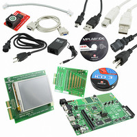
Contents
Dev Board, Display Board, 3 Bare Boards, MPLAB ICD-3, Cables, Power Supply
Processor To Be Evaluated
PIC24FJ256DA210
Data Bus Width
16 bit
Interface Type
RS-232, USB, Ethernet, SPI, UART
Operating Supply Voltage
9 V to 15 V
Silicon Manufacturer
Microchip
Core Architecture
PIC
Core Sub-architecture
PIC24
Silicon Core Number
PIC24F
Silicon Family Name
PIC24FJxxDAxxx
Lead Free Status / RoHS Status
Lead free / RoHS Compliant
For Use With/related Products
PIC24FJ256DA210
Lead Free Status / Rohs Status
Lead free / RoHS Compliant
Available stocks
Company
Part Number
Manufacturer
Quantity
Price
Company:

Part Number:
DV164039
Manufacturer:
MICROCHIP
Quantity:
12 000
Part Number:
DV164039
Manufacturer:
MICROCHIP/微芯
Quantity:
20 000


PIC24FJ256DA210 Development Board User’s Guide
4.4
DS51911A-page 34
SETUP AND CONFIGURATION
The PIC24FJ256DA210 Development Board has been designed with a wide range of
hardware options. These allow the user to evaluate the entire range of the microcon-
troller’s features, include user-defined inputs, explore the range of graphics options,
and incorporate USB connectivity options.
To maintain flexibility, many of the board’s hardware options are configured using stan-
dard jumpers. In a few cases, modifying the board at several locations (by the addition
or removal of resistors) may also be required. Details of the configuration options and
how to select them are provided in the following sections. A list of the development
board’s configuration jumpers is provided in Table 4-1; their corresponding locations
are shown in Figure 4-2.
TABLE 4-1:
FIGURE 4-2:
Key
10
12
13
14
11
1
2
3
4
5
6
7
8
9
1
2
3
Jumper
JP10
JP11
JP12
JP13
JP14
JP15
JP16
JP17
JP23
JP5
JP6
JP7
JP8
JP9
JUMPER SETTINGS AND CONFIGURATION OPTIONS
12
Enables USB OTG
Enables USB Embedded Host mode
Enables USB Device mode
Sets Byte Enable mode for on-board parallel memory
Configures RA1 and RC4 for resistive touch screen (Y-, X+) or
SPI-based touch controller (TC_CS, PEN_INT)
Selects RA7 for LED D4 or PMA17
Configures RD0 for LCD backlight control or serial RX
Configures RG8 as S1 input or CTMU1 input/LED output
Configures RE9 as S2 input or CTMU2 input/LED output
Configures RB5 as S3 input, R3 input, or CTMU3 input/LED output
Selects serial TX channel connection
Selects serial RX channel connection
Selects serial (default) or parallel Flash memory
LOCATION OF DEVELOPMENT BOARD JUMPERS
13
4
14
5
6
7
Function
M
8
2010 Microchip Technology Inc.
10
11
9
Related parts for DV164039
Image
Part Number
Description
Manufacturer
Datasheet
Request
R

Part Number:
Description:
Manufacturer:
Microchip Technology Inc.
Datasheet:
Part Number:
Description:
Manufacturer:
Microchip Technology Inc.
Datasheet:
Part Number:
Description:
Manufacturer:
Microchip Technology Inc.
Datasheet:
Part Number:
Description:
Manufacturer:
Microchip Technology Inc.
Datasheet:
Part Number:
Description:
Manufacturer:
Microchip Technology Inc.
Datasheet:
Part Number:
Description:
Manufacturer:
Microchip Technology Inc.
Datasheet:
Part Number:
Description:
Manufacturer:
Microchip Technology Inc.
Datasheet:
Part Number:
Description:
Manufacturer:
Microchip Technology Inc.
Datasheet: