DV164039 Microchip Technology, DV164039 Datasheet - Page 50
DV164039
Manufacturer Part Number
DV164039
Description
KIT DEV PIC24FJ256DA210
Manufacturer
Microchip Technology
Series
dsPIC™r
Type
MCUr
Specifications of DV164039
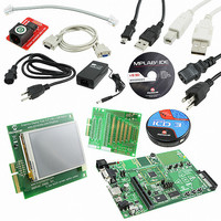
Contents
Dev Board, Display Board, 3 Bare Boards, MPLAB ICD-3, Cables, Power Supply
Processor To Be Evaluated
PIC24FJ256DA210
Data Bus Width
16 bit
Interface Type
RS-232, USB, Ethernet, SPI, UART
Operating Supply Voltage
9 V to 15 V
Silicon Manufacturer
Microchip
Core Architecture
PIC
Core Sub-architecture
PIC24
Silicon Core Number
PIC24F
Silicon Family Name
PIC24FJxxDAxxx
Lead Free Status / RoHS Status
Lead free / RoHS Compliant
For Use With/related Products
PIC24FJ256DA210
Lead Free Status / Rohs Status
Lead free / RoHS Compliant
Available stocks
Company
Part Number
Manufacturer
Quantity
Price
Company:

Part Number:
DV164039
Manufacturer:
MICROCHIP
Quantity:
12 000
Part Number:
DV164039
Manufacturer:
MICROCHIP/微芯
Quantity:
20 000


PIC24FJ256DA210 Development Board User’s Guide
DS51911A-page 50
TABLE A-2:
Legend: Bold text indicates jumper labelling on development board in the absence of
Jumper
JP10
JP11
JP12
JP13
JP14
JP15
JP16
JP17
JP23
JP5
JP6
JP7
JP8
JP9
numbering (JP13 through JP15).
Y- signal of resistive touch screen is connected to RA1 (default)
X+ signal of resistive touch screen is connected to RC4 (default)
Backlight PWM controlled signal (BKLT_PWM) is connected to RD0
Switch S2 connected to AN21/RE9 (default)
Switch S3 connected to AN5/RB5 (default)
Serial TX signal connected to USART_TX of RS-232 level shifter
Serial RX signal connected to USART_RX of RS-232 level shifter
Connect VBUS for USB OTG operation
USB OTG is not used (default)
Connect VBUS for USB Embedded Host operation (default)
Embedded USB Host operation is not used
Connect VBUS for USB Device operation
USB Device operation is not used (default)
Connect PMBE1 to Upper Byte signal of External RAM (U6) (default)
Open, PMBE1 can be used in PICtail™ Plus Expansion Port
SPI touch screen signal TC_CS is connected to RA1
SPI touch screen interrupt PEN_INT is connected to RC4
PMA17/RA7 signal is connected to LED D4 (default)
PMA17/RA7 signal is connected to memory address line 17
Backlight signal BKLT_EN is connected to RD0
Serial RX signal is connected to RD0 (default)
Switch S1 connected to AN19/RG8 (default)
CTMU PAD1 and LED D1 connected to AN19/RG8
CTMU PAD2 and LED D2 connected to AN21/RE9
CTMU PAD3 and LED D3 connected to AN5/RB5
Potentiometer POT R3 connected to AN5/RB5
(default)
Serial TX signal connected to U1TX of PICtail Plus Port
(default)
Serial RX signal connected to U1RX of PICtail Plus Port
PMCS2 signal connected to parallel Flash memory chip select
PMCS2 signal connected to SPI Flash memory chip select (default)
SUMMARY OF ALL JUMPER SELECTIONS
Function
2010 Microchip Technology Inc.
Jumper
Bridged
Bridged
Bridged
Bridged
Setting
Open
Open
Open
Open
1-2
2-3
1-2
2-3
1-2
2-3
1-2
2-3
2-4
1-2
2-3
1-2
2-3
1-2
2-3
2-4
1-2
2-3
1-2
2-3
1-2
2-3
Related parts for DV164039
Image
Part Number
Description
Manufacturer
Datasheet
Request
R

Part Number:
Description:
Manufacturer:
Microchip Technology Inc.
Datasheet:
Part Number:
Description:
Manufacturer:
Microchip Technology Inc.
Datasheet:
Part Number:
Description:
Manufacturer:
Microchip Technology Inc.
Datasheet:
Part Number:
Description:
Manufacturer:
Microchip Technology Inc.
Datasheet:
Part Number:
Description:
Manufacturer:
Microchip Technology Inc.
Datasheet:
Part Number:
Description:
Manufacturer:
Microchip Technology Inc.
Datasheet:
Part Number:
Description:
Manufacturer:
Microchip Technology Inc.
Datasheet:
Part Number:
Description:
Manufacturer:
Microchip Technology Inc.
Datasheet: