101-0523 Rabbit Semiconductor, 101-0523 Datasheet - Page 30
101-0523
Manufacturer Part Number
101-0523
Description
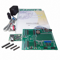
KIT DEV RABBIT3000/RCM3000
Manufacturer
Rabbit Semiconductor
Series
RabbitCore 3000r
Type
MPU Moduler
Datasheet
1.101-0507.pdf
(128 pages)
Specifications of 101-0523
Rohs Status
RoHS non-compliant
Contents
RabbitCore Module, Dev. Board, AC Adapter, Cable and Dynamic C® CD-Rom
Processor To Be Evaluated
RCM3000
Interface Type
RS-232, Ethernet
Maximum Operating Temperature
+ 70 C
Minimum Operating Temperature
- 40 C
Operating Supply Voltage
3.15 V to 3.45 V
For Use With/related Products
RCM3000
Lead Free Status / Rohs Status
Lead free / RoHS Compliant
Other names
316-1017


4.2 Serial Communication
The RCM3000 board does not have an RS-232 or an RS-485 transceiver directly on the
board. However, an RS-232 or RS-485 interface may be incorporated on the board the
RCM3000 is mounted on. For example, the Prototyping Board has a standard RS-232
transceiver chip.
4.2.1 Serial Ports
There are six serial ports designated as Serial Ports A, B, C, D, E, and F. All six serial ports
can operate in an asynchronous mode up to the baud rate of the system clock divided by 16.
An asynchronous port can handle 7 or 8 data bits. A 9th bit address scheme, where an addi-
tional bit is sent to mark the first byte of a message, is also supported. Serial Ports A, B, C,
and D can also be operated in the clocked serial mode. In this mode, a clock line synchro-
nously clocks the data in or out. Either of the two communicating devices can supply the
clock. When the Rabbit 3000 provides the clock, the baud rate can be up to 80% of the sys-
tem clock frequency divided by 128, or 183,750 bps for a 29.4 MHz clock speed.
Serial Ports E and F can also be configured as SDLC/HDLC serial ports. The IRDA proto-
col is also supported in SDLC format by these two ports.
Serial Port A is available only on the programming port.
4.2.2 Ethernet Port
22
Figure 7 shows the pinout for the
RJ-45 Ethernet port (J4). Note that
some Ethernet connectors are num-
bered in reverse to the order used
here.
Two LEDs are placed next to the
RJ-45 Ethernet jack, one to indicate
an Ethernet link (
indicate Ethernet activity (
The Ethernet signals are also avail-
able on header J1.
The transformer/connector assembly ground is con-
nected to the RCM3000 printed circuit board digital
ground via a 0 Ω resistor, R31, as shown in
Figure 8.
The RJ-45 connector is shielded to minimize EMI
effects to/from the Ethernet signals.
LNK
) and one to
ACT
).
Figure 7. RJ-45 Ethernet Port Pinout
Figure 8. Isolation Resistor R31
ETHERNET
RabbitCore RCM3000
Related parts for 101-0523
Image
Part Number
Description
Manufacturer
Datasheet
Request
R

Part Number:
Description:
COMPUTER SNGLBD BL2101 A/D 0-10V
Manufacturer:
Rabbit Semiconductor
Part Number:
Description:
CARD D/A 0-10V SR9400 SMARTSTAR
Manufacturer:
Rabbit Semiconductor
Datasheet:
Part Number:
Description:
CARD A/D 0-10V SR9300 SMARTSTAR
Manufacturer:
Rabbit Semiconductor
Datasheet:

Part Number:
Description:
WiFi / 802.11 Modules & Development Tools WIRELESS CONTROL APP KIT
Manufacturer:
Rabbit Semiconductor

Part Number:
Description:
KIT DEV RABBITCORE RCM3750
Manufacturer:
Rabbit Semiconductor
Datasheet:
Part Number:
Description:
KIT DEV RABBIT 2000 INT'L
Manufacturer:
Rabbit Semiconductor
Datasheet:
Part Number:
Description:
KIT DEV RABBIT RCM2000 INT'L
Manufacturer:
Rabbit Semiconductor
Datasheet:

Part Number:
Description:
KIT DEVELOPMENT RCM3700 INT'L
Manufacturer:
Rabbit Semiconductor
Datasheet:

Part Number:
Description:
BL4S200 TOOL KIT
Manufacturer:
Rabbit Semiconductor
Datasheet:
Part Number:
Description:
MODULE RABBITCORE RCM3720
Manufacturer:
Rabbit Semiconductor
Datasheet:
Part Number:
Description:
MODULE RABBITCORE RCM3220
Manufacturer:
Rabbit Semiconductor
Datasheet:
Part Number:
Description:
MODULE RABBITCORE RCM3210
Manufacturer:
Rabbit Semiconductor
Datasheet:
Part Number:
Description:
COMPUTER SGL-BOARD OP6600 W/SRAM
Manufacturer:
Rabbit Semiconductor
Datasheet:
Part Number:
Description:
COMPUTER SGL-BD BL2000 SRAM/FLSH
Manufacturer:
Rabbit Semiconductor