DEMO9RS08KA8 Freescale Semiconductor, DEMO9RS08KA8 Datasheet - Page 17
DEMO9RS08KA8
Manufacturer Part Number
DEMO9RS08KA8
Description
BOARD DEMO FOR MC9RS08KA8
Manufacturer
Freescale Semiconductor
Series
RS08r
Type
MCUr
Specifications of DEMO9RS08KA8
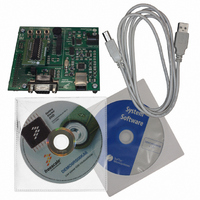
Contents
Board, Adapter, Cable, CD, Documentation
Silicon Manufacturer
Freescale
Core Architecture
RS08
Core Sub-architecture
RS08
Silicon Core Number
MC9RS08
Silicon Family Name
RS08KA
Kit Contents
Board
Rohs Compliant
Yes
For Use With/related Products
MC9RS08KA8
Lead Free Status / RoHS Status
Lead free / RoHS Compliant


5 Operating Modes
5.1 Overview
The Demonstration Board can work in two modes: “standalone” mode and “host” mode.
5.2 Standalone Mode
In standalone mode, no PC connection is required. The microcontroller is factory programmed
with a sample application.
To run the built-in example:
1.
2.
3.
4.
5.
6.
7.
8.
5.3 Host Mode
In host mode the program execution is controlled by the host PC through the “USB” connector.
You can use the PC to debug the application by, for example, executing the program step by
step and watching how the microcontroller registers vary, using the provided CodeWarrior
Development Studio.
Ensure that all of the “ENABLE” jumpers in the “MCU AND I/O” area are inserted.
Ensure that all of the “ENABLE” jumpers in the “SERIAL” area are inserted.
Ensure that the “POWER SEL” jumper selects the “UNREG” position.
Power on the Demonstration Board through the 12 V DC plug-in power supply.
The green “POWER” LED on the board should turn on.
Press the “SW0” push-button. Rotate the potentiometer. The “LED0” will blink with a
frequency related to the potentiometer value.
Press the “SW1” push-button. The “LED1” will blink with a frequency related to amount
of light hitting the photoresistor.
The value of the potentiometer or the light sensor is also sent to the RS-232 port (baud
rate = 9600, data bits = 8, parity = N, stop bits = 1).
Page 15
Related parts for DEMO9RS08KA8
Image
Part Number
Description
Manufacturer
Datasheet
Request
R

Part Number:
Description:
Manufacturer:
Freescale Semiconductor, Inc
Datasheet:
Part Number:
Description:
Manufacturer:
Freescale Semiconductor, Inc
Datasheet:
Part Number:
Description:
Manufacturer:
Freescale Semiconductor, Inc
Datasheet:
Part Number:
Description:
Manufacturer:
Freescale Semiconductor, Inc
Datasheet:
Part Number:
Description:
Manufacturer:
Freescale Semiconductor, Inc
Datasheet:
Part Number:
Description:
Manufacturer:
Freescale Semiconductor, Inc
Datasheet:
Part Number:
Description:
Manufacturer:
Freescale Semiconductor, Inc
Datasheet:
Part Number:
Description:
Manufacturer:
Freescale Semiconductor, Inc
Datasheet:
Part Number:
Description:
Manufacturer:
Freescale Semiconductor, Inc
Datasheet:
Part Number:
Description:
Manufacturer:
Freescale Semiconductor, Inc
Datasheet:
Part Number:
Description:
Manufacturer:
Freescale Semiconductor, Inc
Datasheet:
Part Number:
Description:
Manufacturer:
Freescale Semiconductor, Inc
Datasheet:
Part Number:
Description:
Manufacturer:
Freescale Semiconductor, Inc
Datasheet:
Part Number:
Description:
Manufacturer:
Freescale Semiconductor, Inc
Datasheet:
Part Number:
Description:
Manufacturer:
Freescale Semiconductor, Inc
Datasheet: