101-1157 Rabbit Semiconductor, 101-1157 Datasheet - Page 93
101-1157
Manufacturer Part Number
101-1157
Description
KIT DEVELOPMENT USA RCM4100
Manufacturer
Rabbit Semiconductor
Series
RabbitCore 4000r
Type
MPU Moduler
Datasheet
1.20-101-1093.pdf
(112 pages)
Specifications of 101-1157
Contents
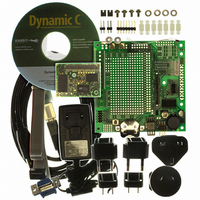
RabbitCore Module, Dev. Board, AC Adapter, Cable and Dynamic C® CD-Rom
Processor To Be Evaluated
Rabbit 4001
Data Bus Width
8 bit
Interface Type
SPI
For Use With/related Products
RCM4100
Lead Free Status / RoHS Status
Lead free / RoHS compliant by exemption
Other names
316-1123


B.4.1 Adding Other Components
There are pads for 28-pin TSSOP devices, 16-pin SOIC devices, and 6-pin SOT devices
that can be used for surface-mount prototyping with these devices. There are also pads that
can be used for SMT resistors and capacitors in an 0805 SMT package. Each component
has every one of its pin pads connected to a hole in which a 30 AWG wire can be soldered
(standard wire wrap wire can be soldered in for point-to-point wiring on the Prototyping
Board). Because the traces are very thin, carefully determine which set of holes is con-
nected to which surface-mount pad.
B.4.2 Measuring Current Draw
The Prototyping Board has a current-measurement feature available at header locations
JP1 and JP2 for the +5 V and +3.3 V supplies respectively. To measure current, you will
have to cut the trace on the bottom side of the Prototyping Board corresponding to the
power supply or power supplies whose current draw you will be measuring. Header loca-
tions JP1 and JP2 are shown in Figure B-5. Then install a 1 × 2 header strip from the
Development Kit on the top side of the Prototyping Board at the header location(s) whose
trace(s) you cut. The header strip(s) will allow you to use an ammeter across their pins to
measure the current drawn from that supply. Once you are done measuring the current,
place a jumper across the header pins to resume normal operation.
User’s Manual
NOTE: Once you have cut the trace below header location JP1 or JP2, you must either be
using the ammeter or have a jumper in place in order for power to be delivered to the
Prototyping Board.
Figure B-5. Prototyping Board Current-Measurement Option
89
Related parts for 101-1157
Image
Part Number
Description
Manufacturer
Datasheet
Request
R

Part Number:
Description:
KIT DEV FOR BL2500 COYOTE
Manufacturer:
Rabbit Semiconductor
Datasheet:

Part Number:
Description:
KIT APPLICATION SIMPLE SENSOR
Manufacturer:
Rabbit Semiconductor
Datasheet:

Part Number:
Description:
KIT DEV RABBITCORE RCM3750
Manufacturer:
Rabbit Semiconductor
Datasheet:

Part Number:
Description:
KIT DEV RABBIT 2000 INT'L
Manufacturer:
Rabbit Semiconductor
Datasheet:
Part Number:
Description:
KIT DEV RABBIT RCM2000 INT'L
Manufacturer:
Rabbit Semiconductor
Datasheet:

Part Number:
Description:
KIT DEVELOPMENT RCM3700 INT'L
Manufacturer:
Rabbit Semiconductor
Datasheet:

Part Number:
Description:
BL4S200 TOOL KIT
Manufacturer:
Rabbit Semiconductor
Datasheet:


Part Number:
Description:
KIT DEVELOPMENT FOR JACKRABBIT
Manufacturer:
Rabbit Semiconductor
Part Number:
Description:
MODULE RABBITCORE RCM3720
Manufacturer:
Rabbit Semiconductor
Datasheet:
Part Number:
Description:
MODULE RABBITCORE RCM3220
Manufacturer:
Rabbit Semiconductor
Datasheet:
Part Number:
Description:
MODULE RABBITCORE RCM3210
Manufacturer:
Rabbit Semiconductor
Datasheet:
Part Number:
Description:
COMPUTER SGL-BOARD OP6600 W/SRAM
Manufacturer:
Rabbit Semiconductor
Datasheet:
Part Number:
Description:
COMPUTER SGL-BD BL2000 SRAM/FLSH
Manufacturer:
Rabbit Semiconductor