EPSILON5-A1 Equinox Technologies, EPSILON5-A1 Datasheet - Page 41
EPSILON5-A1
Manufacturer Part Number
EPSILON5-A1
Description
ISP PORTABLE PROGRAMMER USB
Manufacturer
Equinox Technologies
Series
Epsilon5r
Type
Portable ISPr
Specifications of EPSILON5-A1
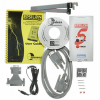
Contents
Programmer, Software, Cables and Documentation
Ic Product Type
In-Circuit Programmer
Features
2Mbits Of On-Board Non-Volatile FLASH Memory For User Project Storage
Interface Type
JTAG
Mcu Supported Families
ATmega And AT91SAM7
Mpu Supported Families
AVR
Rohs Compliant
Yes
External Depth
31mm
Height
189mm
Length
80mm
For Use With/related Products
ATMEL AT89S, AVR, AT91SAM7, NXP P89C51Rx2 P89C66x, Zensys, Serial EEPROM's
Other names
483-1000


Fig. 2.5.4.2 FLASH / EEPROM tab – functional description
#
1
2
3
4
5
6
7
8
9
30
File name and
properties
Re-load file to
buffer
Buffer Control
Buttons
Target Control
Buttons
Signature of
Target Device
Buffer
Address
Buffer Window
CRC
Size
This specifies the ‘File Name / path’ and ‘Last updated’ date of the file to be
loaded into the Buffer Window.
Clicking the
Buffer Window.
This will overwrite any information already in the Buffer Window.
This group of buttons control operations on the EDS – Buffer Window.
This group of buttons control operations on the actual Target Device.
This is the signature (Device ID) which is expected for the Target Device.
This is the address of the currently selected location in the Buffer Window.
The Buffer Window displays a hexidecimal and alphanumeric
representation of the data which has either been loaded from file or read
back from a Target Device.
This is a CRC Checksum of the entire Buffer (ie. from address 0x00000 to
the end address specified in the buffer.
This is the physical address range in bytes of the entire Buffer.
•
•
•
•
•
•
•
•
By default, this will point to the file specified in the associated
Programming Project (*.ppm).
To load a different file, click the <Load> button and browse to the
required file.
To use these buttons or to manually edit the Buffer Window, it is
necessary to check the ‘Edit Buffer’ check box.
This extra step helps to avoid accidental modification of data in the
buffer.
A programmer and suitable Target System must be connected
when using these buttons.
The bytes are grouped into rows of 16 bytes with the start address
of each row displayed in the left-hand column.
The Hexadecimal representation of the 16 bytes is displayed in the
middle column
The ASCII representation of the 16 bytes is displayed in the right-
hand column.
EPSILON5 MKII Programmer - User Guide V1.12 – 1
icon re-loads the specified Flash / EEPROM file into the
st
August 2007
Related parts for EPSILON5-A1
Image
Part Number
Description
Manufacturer
Datasheet
Request
R

Part Number:
Description:
CONVERTER KIT, COMMS, RS485
Manufacturer:
Equinox Technologies
Datasheet:

Part Number:
Description:
MOD PPM3 CONN-3 I/O ATMEGA JTAG
Manufacturer:
Equinox Technologies
Datasheet:

Part Number:
Description:
MODULE FOR PPM3-MK2 I/O DRIVER
Manufacturer:
Equinox Technologies
Datasheet:

Part Number:
Description:
MOD PPM3 SPECIAL FUNCTION DRIVER
Manufacturer:
Equinox Technologies

Part Number:
Description:
MODULE CONVERTER RS232 TO RS485
Manufacturer:
Equinox Technologies

Part Number:
Description:
MODULE CALCON FOR PPMS-MK2
Manufacturer:
Equinox Technologies
Datasheet:

Part Number:
Description:
ISP PORTABLE HS AVR JTAG USB
Manufacturer:
Equinox Technologies
Datasheet:

Part Number:
Description:
ISP PORTABLE HS AT91SAM7 USB
Manufacturer:
Equinox Technologies
Datasheet:

Part Number:
Description:
ISP PORTABLE USB AT91SAM7 UPGRAD
Manufacturer:
Equinox Technologies

Part Number:
Description:
PORTABLE PRODUCTION ISP HS USB
Manufacturer:
Equinox Technologies
Datasheet:

Part Number:
Description:
ISP MULTI PROJECT AVR JTAG USB
Manufacturer:
Equinox Technologies
Datasheet:

Part Number:
Description:
ISP MULTI PROJECT AT91SAM7 USB
Manufacturer:
Equinox Technologies
Datasheet:

Part Number:
Description:
ISP PRODUCTION PROGRAMMER
Manufacturer:
Equinox Technologies
Datasheet:

Part Number:
Description:
ISP PORTABLE AVR JTAG UPGRAD
Manufacturer:
Equinox Technologies
Datasheet:

Part Number:
Description:
PROGRAMMER PORTABLE HI-SPEED ISP
Manufacturer:
Equinox Technologies